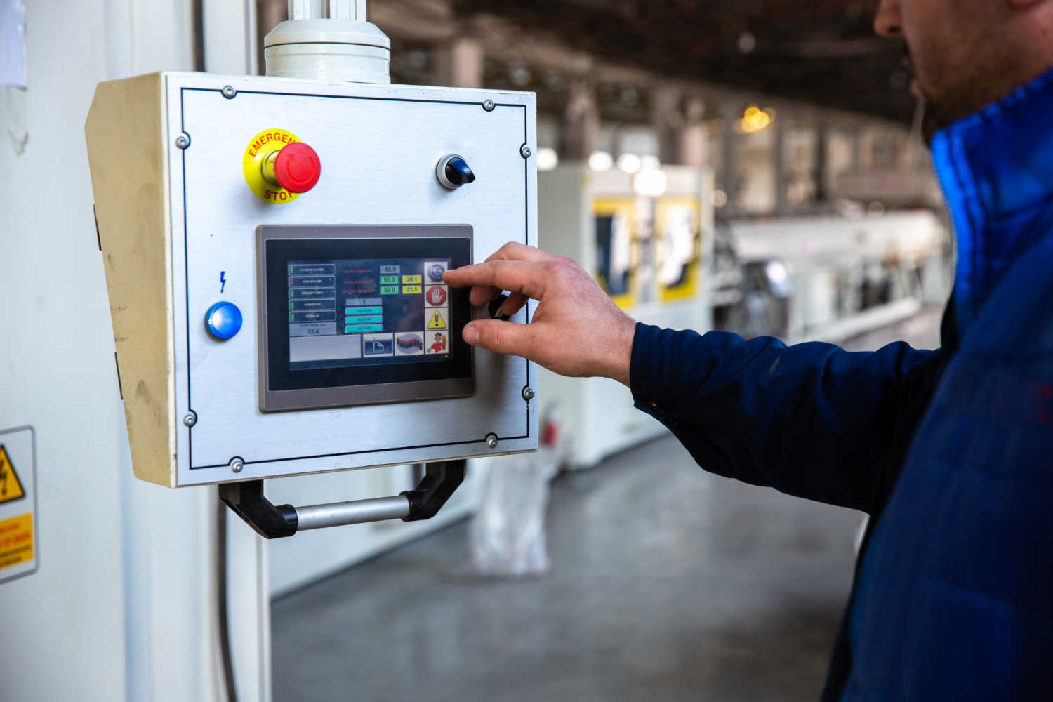
When you need to start medium-to-large three-phase induction motors without punishing the supply network, the star–delta starter is a time-tested solution. It reduces inrush current (typically to ~33% of DOL) by initially connecting the motor windings in star (Y), then—after a timed interval—reconfiguring them to delta (Δ) for full-load operation.
But the real reliability of a star–delta panel doesn’t come from the three contactors and a timer alone. It comes from the protection ecosystem you build around them.
This guide walks through each protection device you should consider, why it matters, and how to size/coordinate it—plus a pre-commissioning checklist and FAQs. Note: Examples below are indicative; always follow your motor nameplate, utility fault levels, and site electrical standards.
1) Where Protection Devices Sit in a Star–Delta Panel
Typical power & control path:
Incoming Supply → Main Isolator/Disconnector → Short-Circuit Protection (HRC fuses/MCCB) → Contactor Set (Line/Main, Star, Delta) + Interlocks → Overload Relay (in motor line) → Motor Terminals
On the control side you’ll see: control MCB/fuse, control transformer (if needed), timer, aux contacts, phase-monitoring relay, earth-fault relay (optional), emergency stop, and surge suppression.
2) Core Protection Devices (Power Circuit)
A) Main Isolator / Load Break Switch (LBS)
Role: Safe manual isolation for maintenance and emergency switching.
Selection: Rated for motor FLA and upstream fault level; choose a device with visible break and padlocking provision.
B) Short-Circuit Protection: HRC Fuses or MCCB
Role: Detect and interrupt high-magnitude faults before they damage contactors, cables, and the motor.
-
HRC Fuses (aM / gG types):
-
aM (motor-rated) offer excellent short-circuit protection while withstanding motor starting surges.
-
gG (general-purpose) protect against both overload & short circuit but may be less forgiving for motor inrush.
-
-
MCCB (Molded-Case Circuit Breaker):
-
Use motor-friendly trip curves and ensure sufficient Icu/Ics for available fault current.
-
Adjustable short-time/instantaneous is helpful for coordination.
-
Quick tip: If you prefer reusability and adjustability → MCCB. If you want ultra-fast limiting and compactness → aM HRC fuses.
C) Thermal Overload Relay (OLR) or Electronic Overload
Role: Protects against overload and prolonged stalling—faults that sit below magnetic/instantaneous thresholds.
-
Setting: Typically 0.9–1.0 × motor FLA (based on nameplate).
-
Compensation: Choose ambient-compensated relays for variable panel temperatures.
-
Class: Trip class 10/20/30 depending on application inertia. Pumps are often Class 10; conveyors might need Class 20.
Placement: OLR is wired so that it protects the motor in both star and delta. Common practice: place it downstream of the main contactor in the line feeding the motor.
D) Motor Protection Circuit Breaker (MPCB) – Optional Alternate
Role: Combines short-circuit and adjustable thermal protection in one unit.
Use case: Compact MCC designs; small to medium motors; simplifies wiring. Ensure compatibility with star–delta topology.
E) Earth-Fault / Ground-Fault Protection
Role: Detects leakage currents to ground; prevents fire and shock hazards.
Implementation: Residual current relay with CBCT (core balance CT) or MCCB with ground-fault module.
Setting: Start around 20–30% of FLA (or per safety standard) with a small delay to avoid nuisance tripping.
F) Under/Over-Voltage & Phase-Monitoring Relay
Role: Protects against phase loss, phase sequence error, under-voltage, over-voltage, and unbalance—classic motor killers.
-
Trip on:
-
Phase failure (single-phasing)
-
Phase reversal (wrong sequence)
-
Voltage unbalance (e.g., >2–3%)
-
Under-voltage (contactors might chatter) / Over-voltage
-
G) Surge Protection / RC Snubbers
Role: Suppress contactor coil voltage spikes and reduce EMI/PLC input errors.
Where: Across contactor coils and sometimes across inductive loads.
3) Control-Side Protection & Reliability
A) Control MCB / Control Fuses
Role: Localized protection for 110/220/415 V AC or 24 V DC control circuits. Use separate MCB/fuse from power feeders to avoid blackouts on minor control faults.
B) Control Transformer (if required)
Role: Derive control voltage (e.g., 110/230 V AC or 24 V DC).
Protection: Primary & secondary fuses/MCBs; consider a PTC (thermistor) or thermal fuse for transformer protection.
C) Industrial Timer (On-Delay for Transition)
Role: Sets the star duration before switching to delta (typ. 8–15 seconds depending on motor and load).
Tip: Use an interlocked timing sequence: Star drops out before Delta picks up (with a short “dead time” of ~50–200 ms).
D) Auxiliary Contacts & Mechanical/Electrical Interlocks
Role: Fail-safe interlocking so Star and Delta can never energize together.
Rule: Use both mechanical (hardware) and electrical (aux contact logic) interlocks.
E) Emergency Stop (E-Stop)
Role: Category-appropriate E-Stop that cuts control power to contactor coils.
Design: Hold-to-run philosophy; mushroom head, latching, prominent placement.
4) Coordination Matters: Type 1 vs Type 2
Motor starters are coordinated per IEC 60947-4-1:
-
Type 1: After a short-circuit event, components may be damaged and require repair/replacement.
-
Type 2: After clearing the fault, the starter can be put back into service with no damage or only minor contact welding (easily separable).
If your process demands high uptime, design for Type 2 coordination by pairing current-limiting fuses/MCCB with contactors/OLRs tested for that coordination class. This often influences the choice of aM fuses and specific contactor/OLR ratings.
5) Sizing & Settings: A Quick, Practical Walkthrough
Assume a 30 kW, 415 V, 50 Hz, 3-phase induction motor; efficiency 92%, PF 0.86.
-
Full-Load Current (approx.)
IFLA≈P3⋅V⋅η⋅PFI_{FLA} \approx \dfrac{P}{\sqrt{3} \cdot V \cdot \eta \cdot \text{PF}}IFLA≈3⋅V⋅η⋅PFP
≈ 30 0001.732⋅415⋅0.92⋅0.86\dfrac{30\,000}{1.732 \cdot 415 \cdot 0.92 \cdot 0.86}1.732⋅415⋅0.92⋅0.8630000 ≈ 54–56 A (use nameplate for exact). -
Overload Relay (OLR) setting:
Set 0.95–1.0 × FLA → ~52–56 A. Choose Class 10 or 20 based on load inertia. -
Short-Circuit Device:
-
Check available fault level at panel (e.g., 25 kA).
-
Choose MCCB with Icu ≥ fault level or aM HRC fuses with adequate breaking capacity.
-
Ensure Type 2 coordination pairing if uptime is critical.
-
-
Contactor Ratings:
-
Use AC-3 duty at motor FLA; the main (line) contactor and delta contactor carry ≈ FLA; star contactor carries ≈ FLA/√3 in most classic schemes.
-
Verify manufacturer application notes for star contactor sizing (some designs use different current paths—don’t assume blindly).
-
-
Timer:
-
Start with 10–12 s in star; adjust during commissioning so the motor reaches near-rated speed before transition (listen for torque dip).
-
-
Phase-Monitoring Relay:
-
Trip on phase loss and sequence error; set unbalance threshold (~2–3%) with a brief delay.
-
-
Earth-Fault Relay:
-
Start at 20–30% of FLA (context-dependent). Coordinate with system earthing and safety policy.
-
6) Optional / Advanced Protection
-
Thermistors (PTC) in Motor Windings + PTC Relay: Direct winding temperature protection—gold standard for critical motors.
-
Bearing Temperature / Vibration Sensors: For high-value rotating assets.
-
Stall / Jam Protection via Electronic Overload: Detects locked-rotor or jam conditions quickly.
-
Load-Shedding Input: To gracefully stop motors during brownouts.
-
Surge Protection Devices (SPD) on Supply: For lightning-prone sites.
7) Pre-Commissioning Checklist (Copy–Paste Ready)
-
Isolation: Main disconnector locks and visibly isolates.
-
Short-Circuit Device: MCCB/fuse ratings verified against fault level; terminals torqued.
-
Overload: OLR range matches FLA; class chosen; test trip done.
-
Contactors: AC-3 ratings adequate; mechanical interlock between Star & Delta; arc chutes clean.
-
Wiring: Correct star/delta bridge connections; control wiring ferruled and labeled.
-
Timer: Star time set; verify break-before-make with a small dead time.
-
Phase Relay: Trips on loss/reversal/unbalance; tested with simulated fault.
-
Earth-Fault: CBCT orientation and relay setting verified.
-
Control Power: Separate control MCB/fuses; transformer protected both sides.
-
E-Stop: Latching, tested; starter cannot re-energize automatically after E-Stop reset unless designed.
-
Documentation: SLD, control schematic, settings sheet, and maintenance log completed.
8) Common Pitfalls (and How to Avoid Them)
-
Star & Delta ON together: Always use both mechanical and electrical interlocks.
-
Nuisance trips during transition: Add dead time; check timer contacts; ensure no contact overlap.
-
Undersized star contactor: Validate current through star leg; follow the manufacturer’s star–delta application notes.
-
Overload set too low/high: Calibrate to nameplate FLA; account for ambient.
-
Phase-loss ignored: Always include a phase-monitoring relay—single-phasing can burn the motor quickly.
-
No earthing/poor bonding: Earth the motor frame, panel, doors, gland plates; test continuity.
9) Why Choose BCH Electric for Star–Delta Starters in India
If you’re building or upgrading star–delta panels, BCH Electric is a dependable partner for Indian industrial conditions:
-
Complete Motor-Starting Portfolio: Contactors, thermal/electronic overloads, MPCBs/MCCBs, HRC fuse bases, phase-monitoring relays, timers, and factory-assembled star–delta starters—ensuring compatibility and coordination.
-
Built for Indian Environments: Robust designs for dust, heat, and voltage fluctuations commonly seen across Indian plants.
-
Standards-Aligned Quality: Products designed to comply with relevant IEC/IS standards for motor control and protection.
-
Service & Availability: Strong distribution and support network—quick spares, replacements, and technical guidance.
Bottom line: With BCH Electric, you can source the entire protection stack around your star–delta starter from one proven manufacturer—simplifying coordination, procurement, and after-sales support.
10) FAQs
Q1: Can I use an MPCB instead of MCCB + OLR?
Yes—for small/medium motors an MPCB can simplify wiring. Ensure it supports star–delta applications and has the right short-circuit capacity.
Q2: What’s a good starting point for star time?
Try 10–12 s and fine-tune on site. The goal is to reach near-rated speed before transition, avoiding torque dips.
Q3: Do I still need a phase-monitoring relay if I have a VFD?
In a VFD system, phase issues are handled differently, but for a star–delta starter (across-the-line), yes—use a phase-monitoring relay.
Q4: Which is better—HRC fuses or MCCB?
For Type 2 coordination and very high fault levels, HRC aM fuses often excel. MCCBs offer adjustability and quick reset. Many panels combine the strengths of both strategies across feeders.
11) Ready-to-Use Template: Settings Sheet (Excerpt)
-
Motor: ___________ kW, ______ V, ______ Hz, FLA: ______ A
-
OLR: Range ______ A; Set at ______ A; Trip Class: 10 / 20 / 30
-
Short-Circuit Device: MCCB/Fuse; Rating ______ A; Icu/Ics or fuse class: ______
-
Phase Relay: U/O-V setpoints ______%; Unbalance ______%
-
Earth-Fault Relay: ______ A / ______ ms
-
Timer: Star time ______ s; Dead time ______ ms
-
Interlocks Verified: Mechanical ✅ Electrical ✅
-
E-Stop Tested: ✅
-
Commissioned By / Date: __________________
Final Word
A star–delta starter is only as reliable as its protection scheme and coordination. Get the isolator, short-circuit device, overload, phase monitoring, and earth-fault protection right—then validate with on-site trials. For Indian plants looking for a single-source, standards-aligned solution, BCH Electric offers the products and support to build rugged, efficient star–delta starters that stay online and protect your assets.


