
Power factor plays a crucial role in the efficiency of electrical systems, especially in industrial and commercial facilities. A low power factor leads to higher electricity bills, increased losses, and penalties from utility providers. To improve power factor, industries use capacitor banks or APFC panels, which require accurate calculation of KVAR (Kilovolt-Ampere Reactive).
Understanding how to calculate the required KVAR for power factor correction is essential for designing an efficient electrical system.
In this guide, we explain how to calculate KVAR for power factor correction, along with formulas, examples, and practical insights for industrial applications.
What Is Power Factor?
Power factor (PF) is the ratio of active power (kW) to apparent power (kVA).
Formula:
PowerFactor(PF)=kWkVAPower Factor (PF) = \frac{kW}{kVA}
It indicates how efficiently electrical power is being used.
Types of Power:
- Active Power (kW) → Actual useful power
- Reactive Power (kVAR) → Power required for magnetic fields
- Apparent Power (kVA) → Total power supplied
Why Power Factor Correction Is Important
Low power factor results in:
- Higher electricity bills
- Increased current flow
- Power losses in cables
- Voltage drops
- Utility penalties
Improving power factor helps:
- Reduce energy costs
- Improve system efficiency
- Increase equipment life
- Avoid penalties
What Is KVAR in Power Factor Correction?
KVAR (Kilovolt-Ampere Reactive) represents reactive power in the system.
Capacitors supply reactive power locally, reducing the demand from the utility and improving power factor.
Basic Formula to Calculate Required KVAR
The most widely used formula for power factor correction is:
KVAR=kW×(tanϕ1−tanϕ2)KVAR = kW \times (\tan \phi_1 – \tan \phi_2)
Where:
- kW = Active power
- φ₁ = Initial power factor angle
- φ₂ = Desired power factor angle
Step-by-Step Calculation
Step 1: Identify Existing Power Factor
Measure or obtain the current power factor of the system.
Example:
- Existing PF = 0.75
Step 2: Define Target Power Factor
Most industries aim for:
- 0.95 to 0.99
Example:
- Target PF = 0.95
Step 3: Convert Power Factor to Angle
Use:
ϕ=cos−1(PF)\phi = \cos^{-1}(PF)
Example:
- φ₁ = cos⁻¹(0.75) ≈ 41.4°
- φ₂ = cos⁻¹(0.95) ≈ 18.2°
Step 4: Calculate Tangent Values
- tan φ₁ ≈ 0.88
- tan φ₂ ≈ 0.33
Step 5: Apply KVAR Formula
KVAR=kW×(0.88−0.33)KVAR = kW \times (0.88 – 0.33)
If load = 100 kW:
KVAR=100×0.55=55 KVARKVAR = 100 \times 0.55 = 55 \, KVAR
Required capacitor size = 55 KVAR
Simplified Formula for Practical Use
A simplified version often used by engineers:
KVAR=kW×(PFfactor)KVAR = kW \times (PF_{factor})
Where PF factor is derived from standard tables.
Quick Reference Table for KVAR Calculation
| Existing PF | Target PF | KVAR Required per kW |
|---|---|---|
| 0.70 → 0.95 | 0.95 | 0.69 |
| 0.75 → 0.95 | 0.95 | 0.55 |
| 0.80 → 0.95 | 0.95 | 0.43 |
| 0.85 → 0.95 | 0.95 | 0.31 |
| 0.90 → 0.95 | 0.95 | 0.16 |
Multiply the factor with kW load to get KVAR.
Example Calculation for Industrial Load
Given:
- Load = 250 kW
- Existing PF = 0.80
- Target PF = 0.95
From table:
- KVAR factor ≈ 0.43
KVAR=250×0.43=107.5 KVARKVAR = 250 \times 0.43 = 107.5 \, KVAR
Required capacitor bank ≈ 110 KVAR
Types of Power Factor Correction Systems
1. Fixed Capacitor Banks
- Installed permanently
- Suitable for constant loads
2. Automatic Power Factor Correction (APFC) Panels
- Automatically adjust capacitor steps
- Ideal for varying loads
3. Individual Motor Capacitors
- Installed directly with motors
- Reduces reactive power locally
Factors Affecting KVAR Requirement
1. Load Variation
Fluctuating loads require dynamic correction systems like APFC panels.
2. Harmonics in System
Non-linear loads (VFDs, UPS) generate harmonics, affecting capacitor performance.
Special harmonic filters may be required.
3. System Voltage
Voltage variations impact reactive power requirements.
4. Operating Hours
Continuous operations benefit more from power factor correction.
Benefits of Proper KVAR Calculation
Accurate KVAR sizing ensures:
- Optimal capacitor performance
- Improved power factor
- Reduced energy losses
- Avoidance of overcompensation
- Lower electricity bills
Common Mistakes to Avoid
Avoid these common errors:
- Over-sizing capacitor banks
- Ignoring load variation
- Not considering harmonics
- Incorrect PF measurement
- Using fixed capacitors for dynamic loads
Improper calculation can lead to:
- Leading power factor
- Voltage instability
- Equipment damage
Role of APFC Panels in Industrial Systems
Automatic Power Factor Correction panels are widely used in industries to maintain optimal PF.
They:
- Monitor real-time PF
- Switch capacitor banks automatically
- Maintain PF near unity
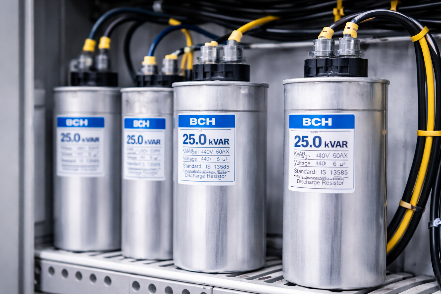
Solutions from BCH India are designed to support efficient power management in industrial systems.
How BCH India Supports Power Factor Correction
BCH India offers electrical solutions for industrial power management, including components used in:
- Capacitor banks
- APFC panels
- Motor control systems
Through https://bchindia.com/, professionals can access:
- Technical guidance
- Product specifications
- Industrial electrical solutions
This helps engineers design efficient power factor correction systems.
Future Trends in Power Factor Correction
Power systems are evolving with:
- Smart APFC panels
- IoT-based monitoring
- Energy analytics systems
- Automated load management
These technologies improve energy efficiency and reduce operational costs.
Conclusion
Calculating the required KVAR for power factor correction is essential for improving electrical system efficiency and reducing energy costs.
By following the correct calculation steps and understanding system requirements, industries can:
- Improve power factor
- Reduce losses
- Avoid penalties
- Enhance equipment performance
Whether using fixed capacitors or advanced APFC panels, proper sizing ensures optimal results.
For more technical insights and electrical solutions, visit https://bchindia.com/.