
When engineers troubleshoot a protection or motor-control circuit, the symptom often appears simple: a trip, a noisy device, a hot terminal or a motor that will not start cleanly. The cause usually sits one or two steps earlier in the electrical chain.
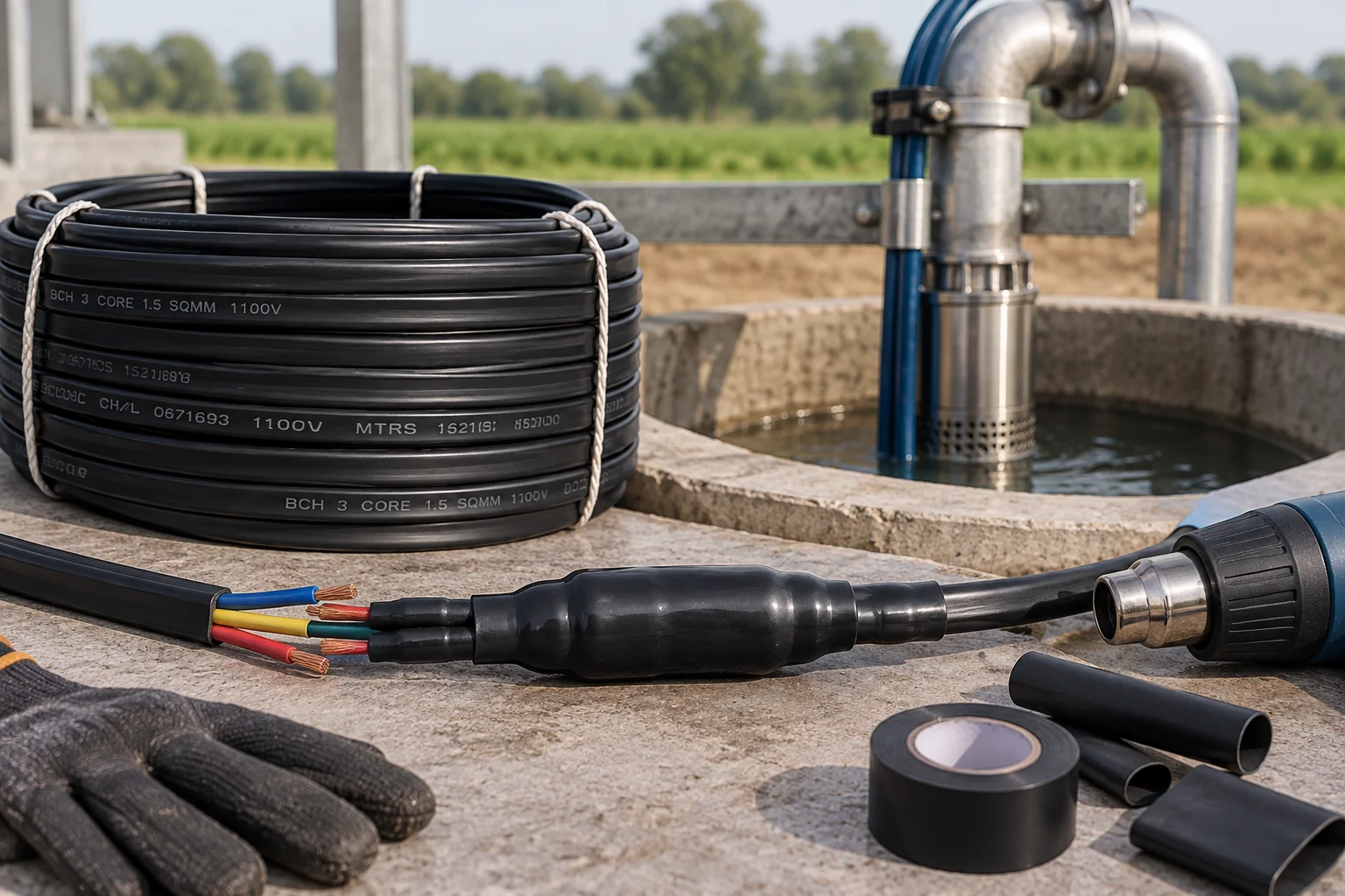
This guide focuses on waterproof jointing of 3 core flat cables for submersible pumps. It is written for engineers, panel builders, contractors and maintenance teams who need to connect the specification with what actually happens in service.
Why submersible cable joints fail
A cable joint in or near a borewell must do more than provide electrical continuity. It must resist moisture ingress, mechanical strain and long-term movement while maintaining insulation between conductors.
A joint can appear satisfactory during installation and still fail later if water tracks along the conductor strands or if the splice has no strain relief.
The electrical connection comes first
Conductors should be joined with a connector or crimping method suitable for the conductor material and current. A poor crimp creates resistance and heat, and no amount of outer sealing can compensate for a weak electrical joint.
Avoid cutting conductor strands to force them into an undersized connector. That reduces effective conductor area and weakens the joint mechanically.
Sealing must stop water migration
The insulation system around the splice must prevent water from reaching the conductor interface. Approved heat-shrink, resin or purpose-made submersible joint kits are commonly used depending on the installation.
Follow the kit sequence carefully: surface preparation, staggered joints where required, full shrink or resin cure, and sealing over the outer sheath are all important.
Provide strain relief and a clean cable route
The electrical splice should not carry the mechanical weight of the pump assembly. Cable support and fastening should prevent repeated bending or pulling at the joint.
Sharp edges, poorly placed clamps and excessive tie pressure can damage the flat cable even when the joint itself is waterproof.
Selection and installation checklist
Start with the actual circuit data rather than a rule of thumb. Record supply voltage, load current, conductor size, upstream and downstream protective devices, operating duty and the environmental conditions around the equipment.
Do not change a protection setting simply to stop repeated trips. A higher threshold can hide an overloaded conductor, a motor problem or a coordination error. The correct response is to identify why the device is operating and then confirm the setting against the equipment and circuit design.
Where the required calculation, test or adjustment affects protection against shock, fire or short circuit, the work should be carried out by a qualified electrical professional using the manufacturer’s instructions and the applicable installation standard.
How this fits into the wider protection system
This topic should not be treated in isolation. 3 Core Flat Cable selection interacts with upstream protection, downstream equipment, conductors and the operating duty of the load. A well-coordinated system is usually easier to troubleshoot because each device has a clear job and its settings are documented.
For related BCH guidance and product information, review the linked resources in the paragraph below.
Related BCH resources
For deeper product and application context, see BCH 3 core flat cable, wires and cables and common flat cable failures.
What to verify before the pump is lowered
The easiest time to catch a cable problem is before the pump enters the borewell. Confirm conductor size and total route length, inspect the sheath for cuts or flattening, verify phase identification and check every joint and termination for mechanical security and sealing.
A continuity and insulation-resistance check provides a useful baseline. Record the results together with the cable length, motor rating and starter details. If the installation later develops a fault, those records help determine whether insulation quality or conductor resistance has changed.
Support points also deserve attention. The cable should follow the rising pipe without sharp bends, crushing ties or unsupported sections that place load on the joint. Good electrical work can still fail early if the cable is mechanically damaged during installation.
How cable problems show up in the starter and motor
Cable faults do not always appear as a complete open circuit. A high-resistance joint can reduce motor terminal voltage, extend starting time and make the contactor or overload relay appear to be the problem. Moisture ingress can create intermittent leakage that worsens as the installation heats or moves.
Compare supply voltage with voltage at the accessible motor circuit points under starting and running conditions, and measure current in each conductor. A combination of low starting voltage and prolonged high current often points toward excessive voltage drop or a motor/load problem rather than a simple starter setting issue.
When the pump must be removed for investigation, keep the fault-finding sequence documented. Replacing the cable without identifying a poor jointing method or mechanical damage point can lead to the same failure after reinstallation.
Questions to answer before final selection or adjustment
Before cable selection, collect motor full-load current, starting method, total one-way cable route, supply voltage and installation environment. The borewell depth alone is not the complete route because surface runs, bends and termination lengths add resistance too.
Cable condition should be considered from a mechanical as well as an electrical perspective. During lowering, the cable may rub against pipe couplings, clamps or borewell edges. Repeated abrasion or crushing can damage the sheath without producing an immediate electrical fault.
Joint locations should be planned rather than improvised. Every joint adds another point where conductor resistance, water sealing and mechanical support must remain reliable for years. Where a joint is unavoidable, use a method intended for submersible service and keep it away from unnecessary mechanical stress.
Commissioning records are particularly useful for borewell systems because access becomes difficult after installation. Cable length, conductor size, insulation-resistance readings, motor current and starter settings create a baseline that can prevent unnecessary pump removal during later troubleshooting.
Additional field considerations
Cable replacement decisions should consider the complete failure path. If insulation damage occurred at a clamp, bend or joint, fitting a new cable without changing that installation detail can reproduce the same fault. Photographing the damaged section and marking its depth or location can make the corrective action much more specific.
Where voltage drop is close to the acceptable limit, also consider supply variation. A cable that works comfortably at nominal voltage may create weak starting when the incoming supply is already low. Designing some margin into conductor selection is generally more robust than relying on ideal supply conditions every time the pump starts.
Common mistakes to avoid
One common mistake is to solve a symptom by increasing a current setting or moving to a slower protection characteristic without checking the underlying fault. That can stop nuisance tripping while reducing the safety margin the protective device was selected to provide.
Another is to compare devices only by one headline rating. Protection equipment is selected as a combination of current, voltage, poles, fault level, time-current behaviour, load duty and installation conditions. Leaving one of those out can make an otherwise reasonable selection behave badly in service.
Finally, do not assume that two devices with similar front labels are interchangeable. Manufacturer curves, tested coordination combinations, terminal limits and environmental derating can differ. Replacement should preserve the original protection intent, not merely fit the available space.
A practical decision framework
Before changing a device or setting, define the operating condition that must be allowed and the fault condition that must be interrupted. Then collect the numbers that separate those two conditions: normal current, starting or inrush current, conductor capacity, prospective short-circuit current, operating time, ambient temperature and any relevant leakage or phase-imbalance data.
Next, compare those values with the manufacturer curves and coordination information. The goal is not to make the protective device insensitive. It is to create enough margin for normal operation while ensuring faults are cleared within the required limits.
After commissioning, record the final device type, rating and adjustable settings. Good records reduce guesswork during later troubleshooting and make it easier to spot when a replacement or field adjustment has changed the original design.
Frequently Asked Questions
Why is 3 core flat cable commonly used for submersible pumps?
Its flat profile can suit routing alongside rising pipes in borewells, while purpose-designed insulation and sheath materials are selected for wet and mechanically demanding installations.
Does a longer pump cable require a larger conductor?
Often it can, because voltage drop increases with conductor resistance and length. Final sizing must also account for motor current, starting behaviour, installation conditions and permissible voltage drop.
Can a cable joint cause motor starting problems?
Yes. A high-resistance joint adds voltage drop and heat. Poor sealing can also allow moisture ingress that progressively reduces insulation quality.
What is the main risk of a poor submersible cable termination?
Loose or damaged terminations can create heat, voltage drop, water ingress and intermittent faults, all of which can shorten cable or motor life.
Should a pump cable be insulation-tested before installation?
Testing before lowering the pump can establish a useful baseline and can catch damaged cable, joints or terminations before access becomes difficult.
Is flat cable always better than round cable?
No. Cable shape is only one factor. The selected cable must be suitable for the pump, voltage, current, route, mechanical conditions and wet environment.
Conclusion
Waterproof Jointing of 3 Core Flat Cables for Submersible Pumps is easiest to manage when the circuit is treated as a system rather than a collection of independent ratings. Use measured operating data, manufacturer curves and documented coordination to keep normal operation reliable without weakening fault protection.
