
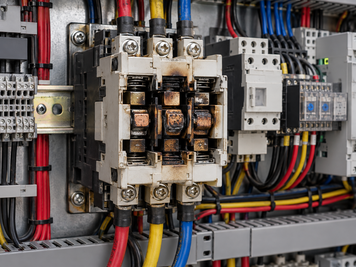
Selection becomes easier when the rating is connected to a real event in the circuit. Instead of treating catalogue terms as isolated specifications, it helps to ask what each setting or construction feature is expected to do during starting, normal running and fault conditions.
This guide focuses on why do contactor contacts burn or weld? causes and prevention. It is written for engineers, panel builders, contractors and maintenance teams who need to connect the specification with what actually happens in service.
Arcing is normal; excessive arcing is not
Every time a contactor interrupts current, an arc forms as the contacts separate. The device is designed to manage that arc within its rated utilization category. Trouble starts when the actual switching duty exceeds what the contactor was selected to handle.
High inrush, plugging, inching, frequent starts or switching a load under conditions different from the nameplate duty can accelerate erosion and raise contact temperature.
Why contacts weld
A very high making current can produce enough heat and electromagnetic force for contact surfaces to fuse together. Short-circuit current is an obvious cause, but severe inrush or a contactor that closes incompletely can also create damaging conditions.
Correct short-circuit protective device coordination is therefore important. A contactor is not intended to interrupt the same fault current as an MCCB or fuse unless the tested starter combination says otherwise.
Why contacts burn or overheat
Contact resistance rises as surfaces become worn, contaminated or mechanically damaged. Loose power terminals add further resistance outside the contact interface. Both effects convert current into heat at a local point.
A contactor selected only by motor kilowatts can also be wrong if the utilization category or starts-per-hour duty is ignored. The load type determines how severe the switching event is.
Prevention starts with duty-based selection
Use the manufacturer’s ratings for the actual utilization category, operating voltage and switching frequency. Confirm coil voltage so the contactor closes fully, and maintain terminal torque and panel cleanliness.
Contacts should not be filed or modified unless the manufacturer’s maintenance instructions explicitly allow it. Modern contact materials are engineered surfaces, and improvised dressing can make performance worse.
Troubleshooting and selection checklist
Start with the actual circuit data rather than a rule of thumb. Record supply voltage, load current, conductor size, upstream and downstream protective devices, operating duty and the environmental conditions around the equipment.
Do not change a protection setting simply to stop repeated trips. A higher threshold can hide an overloaded conductor, a motor problem or a coordination error. The correct response is to identify why the device is operating and then confirm the setting against the equipment and circuit design.
Where the required calculation, test or adjustment affects protection against shock, fire or short circuit, the work should be carried out by a qualified electrical professional using the manufacturer’s instructions and the applicable installation standard.
How this fits into the wider protection system
This topic should not be treated in isolation. Contactor selection interacts with upstream protection, downstream equipment, conductors and the operating duty of the load. A well-coordinated system is usually easier to troubleshoot because each device has a clear job and its settings are documented.
For deeper product and application context, see BCH contactors, AC-1, AC-3 and AC-4 contactor ratings and overload relays.
What to verify during commissioning
Before a contactor is put into regular service, confirm the main-contact rating, utilization category, coil voltage and auxiliary-contact arrangement against the control drawing. Energise the control circuit and check that the contactor pulls in positively without chatter, then confirm that it releases cleanly when the control signal is removed.
Check terminal tightness using the manufacturer procedure and make sure the conductors are supported so their weight does not twist the device terminals. On reversing or interlocked starters, prove the electrical and mechanical interlocks through the intended sequence rather than checking each contactor independently.
For machines with frequent starts, record the expected operations per hour and compare them with the contactor duty data. This is often missed at commissioning even though it has a direct effect on contact temperature and electrical life.
How to separate a control fault from a power-circuit fault
If a contactor fails to operate, first ask whether the coil is receiving the correct control voltage. A healthy power circuit cannot close if the control chain is open, while a healthy coil cannot deliver power reliably if the main contacts or terminals are damaged.
A voltage measurement across the coil while the command is present helps separate the two sides. Correct coil voltage with no pull-in points toward the coil or mechanism; low or missing voltage directs attention to pushbuttons, PLC outputs, interlocks, fuses, control transformers and wiring.
When the contactor closes but the load behaves abnormally, compare voltage and current across all phases and inspect the main contacts and terminals. Keeping control and power diagnostics separate prevents random replacement of devices that are not actually faulty.
Questions to answer before final selection or adjustment
For a new contactor application, capture load type, operating current, utilization category, switching frequency, expected starts per hour and the control-supply voltage. These details describe the electrical stress more accurately than motor power alone.
The control circuit deserves equal attention. Identify which device energises the coil, the available pickup voltage at the farthest wiring point, and the behaviour required after a supply interruption. Long control runs and several series interlocks can produce enough voltage drop to affect pickup even when the nominal control supply is correct.
Where two contactors interact, as in reversing or changeover arrangements, document interlocking logic and prove it during commissioning. A circuit can appear correct in normal sequence yet still allow an unsafe overlap if one auxiliary contact fails or the mechanical interlock is omitted.
Finally, plan inspection around the real number of operations. A contactor in a frequently cycling machine accumulates electrical wear much faster than one used as an occasional isolating switch, even when both carry the same running current.
Additional field considerations
Replacement contactors also need a full rating check. A device with the same physical width or current marking may have a different utilization-category rating, coil voltage, auxiliary-contact arrangement or permissible switching frequency. A like-for-like mechanical fit is not necessarily an electrical equivalent.
For recurring failures, keep the failed device as evidence until the cause is understood. Contact erosion pattern, coil condition and terminal discoloration can show whether the dominant stress came from switching duty, low coil voltage, a loose connection or fault current. Throwing the old device away immediately can remove the best clue to why the replacement might fail again.
Common mistakes to avoid
One common mistake is to solve a symptom by increasing a current setting or moving to a slower protection characteristic without checking the underlying fault. That can stop nuisance tripping while reducing the safety margin the protective device was selected to provide.
Another is to compare devices only by one headline rating. Protection equipment is selected as a combination of current, voltage, poles, fault level, time-current behaviour, load duty and installation conditions. Leaving one of those out can make an otherwise reasonable selection behave badly in service.
Finally, do not assume that two devices with similar front labels are interchangeable. Manufacturer curves, tested coordination combinations, terminal limits and environmental derating can differ. Replacement should preserve the original protection intent, not merely fit the available space.
A practical decision framework
Before changing a device or setting, define the operating condition that must be allowed and the fault condition that must be interrupted. Then collect the numbers that separate those two conditions: normal current, starting or inrush current, conductor capacity, prospective short-circuit current, operating time, ambient temperature and any relevant leakage or phase-imbalance data.
Next, compare those values with the manufacturer curves and coordination information. The goal is not to make the protective device insensitive. It is to create enough margin for normal operation while ensuring faults are cleared within the required limits.
After commissioning, record the final device type, rating and adjustable settings. Good records reduce guesswork during later troubleshooting and make it easier to spot when a replacement or field adjustment has changed the original design.
Frequently Asked Questions
Is a buzzing contactor always defective?
No. Audible noise can result from low control voltage, mechanical contamination, coil problems or normal electromagnetic operation depending on the design. A change in sound or visible chatter should be investigated.
Can I choose a contactor only from motor kW?
Motor power is only one input. Operating voltage, utilization category, duty, starts per hour, ambient conditions and coil voltage also matter.
Why does coil voltage matter if the main contacts are correctly rated?
The coil creates the magnetic force that closes the contactor. Incorrect coil voltage can cause failure to pick up, chatter, overheating or premature contact wear even when the power contacts are properly sized.
Are auxiliary contacts suitable for motor current?
No. Auxiliary contacts are intended for control and signalling duties. Their ratings are much lower than the main power contacts and must be checked for the control load.
Can worn contactor contacts simply be filed smooth?
Not unless the manufacturer specifically permits it. Contact materials and surface profiles are engineered, and improvised filing can reduce performance or contact life.
When should a contactor be replaced?
Replacement is appropriate when there is severe contact erosion or welding, damaged insulation, unreliable mechanical operation, a failed coil or defects that cannot be corrected within manufacturer maintenance instructions.
Conclusion
Why Do Contactor Contacts Burn or Weld? Causes and Prevention is easiest to manage when the circuit is treated as a system rather than a collection of independent ratings. Use measured operating data, manufacturer curves and documented coordination to keep normal operation reliable without weakening fault protection.
