
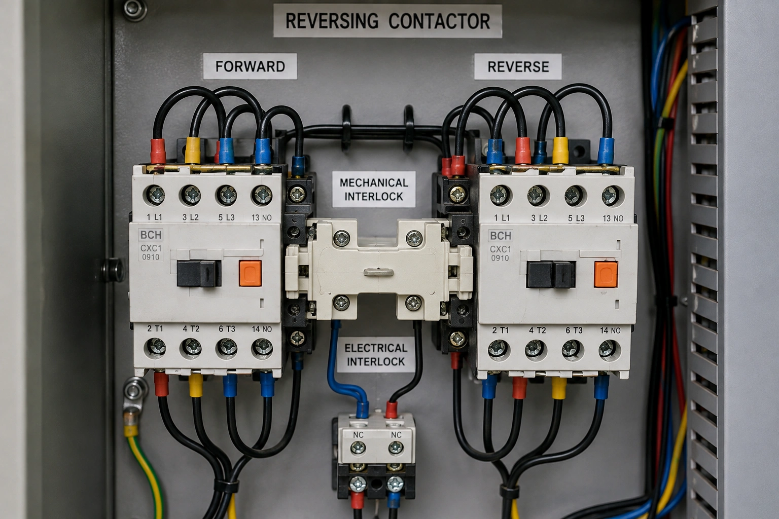
What is reversing contactor interlocking?
A reversing contactor circuit changes a three-phase motor’s direction by changing the phase sequence through separate forward and reverse contactors. The critical rule is that both contactors must not close at the same time. A dependable design therefore uses a hardwired electrical interlock and a compatible mechanical interlock, with PLC or relay logic used as an additional control layer rather than the only barrier. For product-family context, review BCH India’s contactor range while keeping the final selection tied to the motor duty, utilisation category, fault level and approved coordination data.
Why can simultaneous forward and reverse closure be dangerous?
In a conventional reversing arrangement, two motor phases are crossed in the reverse path. If the forward and reverse contactors close together, the power circuit can create a phase-to-phase fault path. That is why interlocking is a circuit requirement, not a convenience feature. The control design must remain safe through normal commands, loss and return of control power, welded or slow auxiliary contacts, wiring mistakes and maintenance substitutions.
BCH’s contactor selection guide for industrial motor control is a useful companion when the reversing function is only one part of a wider motor-control selection. The interlock design does not remove the need to verify current rating, switching duty, coil/control voltage and short-circuit coordination for the exact devices being used.
Electrical vs mechanical interlocking: what does each layer do?
| Interlock layer | Primary function | What it does not replace |
| Normally closed auxiliary contact | Blocks the opposite coil while one contactor is energised | Mechanical prevention, short-circuit protection or correct device selection |
| Mechanical interlock | Physically prevents both contactors from closing together | Correct control wiring or electrical interlocking |
| PLC / relay logic | Controls sequence, permissives and reversal delay | Hardwired prevention appropriate to the risk |
| Contactor feedback | Confirms whether the commanded contactor actually changed state | Primary interlocking or protective switching |
The strongest arrangement is layered. The normally closed auxiliary contact of the forward contactor is placed in series with the reverse coil circuit, and the reverse auxiliary contact is placed in series with the forward coil circuit. A mechanical interlock then provides physical separation between the two contactors. PLC logic can add command validation, timing and feedback alarms, but software should not be treated as the only means of preventing simultaneous closure where a hardwired interlock is required.
When does the reversal delay matter?
A motor or driven machine may still be rotating when the opposite direction is commanded. Immediate reversal can create high electrical and mechanical stress because the motor is being asked to develop torque against existing motion. The required delay depends on inertia, load torque, stopping method and the intended operating duty. A conveyor used for occasional jam clearing is different from a machine designed for frequent reversing.
When frequent reversing or plugging is part of normal operation, check the applicable utilisation category rather than assuming a standard motor duty is adequate. BCH’s guide to AC-1, AC-3 and AC-4 contactor ratings provides the right context for understanding why switching duty matters to contact life and selection.
What should engineers verify before selecting the two contactors?
- Motor rated voltage, nameplate current and connection.
- Starting method, acceleration time, starts per hour and expected reversals per hour.
- Load inertia and whether reversal happens only after stopping or while the machine is still moving.
- Required utilisation category and manufacturer data for the exact contactor reference.
- Coil/control voltage, auxiliary-contact arrangement and mechanical-interlock compatibility.
- Overload protection placement and short-circuit protective device coordination.
- Prospective fault current at the panel and conductor short-circuit withstand.
- Enclosure temperature, ventilation, dust, vibration and terminal conditions.
The contactor is only one element of the starter. BCH’s explanation of how motor starters work with contactors and overload relays helps keep the selection at system level. Where overload protection is being reviewed separately, use the current BCH overload relay range and the exact coordination information for the chosen combination.
How should electrical interlocking be wired and tested?
- Wire the forward command through a normally closed auxiliary contact of the reverse contactor.
- Wire the reverse command through a normally closed auxiliary contact of the forward contactor.
- Fit the approved mechanical interlock between compatible forward and reverse contactors.
- Add the required stop circuit, overload contact and any process permissives without bypassing the hardwired interlock.
- If a PLC is used, program reversal logic and feedback monitoring as a supervisory layer.
- With power isolated, prove that mechanical movement of one contactor prevents the other from closing.
- During controlled commissioning, verify forward operation, stop behaviour, reversal timing and the response to conflicting commands.
- Record device references, auxiliary-contact assignments, settings and test results on the final drawing or panel record.
What mistakes create the most reversing-starter risk?
| Mistake | Why it is risky | Better practice |
| Relying only on PLC logic | Output faults, wiring errors or software changes can defeat the intended sequence | Retain suitable hardwired electrical and mechanical interlocking |
| Selecting by motor kW alone | Does not capture switching duty, reversal frequency or fault conditions | Use actual motor current, utilisation category and duty |
| No reversal delay review | The machine may still be rotating when the opposite contactor is commanded | Check inertia, stop time and process requirements |
| Substituting one contactor independently | Auxiliary and mechanical interlock compatibility may change | Verify the complete pair and accessories |
| Resetting or retesting without evidence | Intermittent faults can be lost | Record state, timing, indications and measurements |
How do MPCB, overload relay and contactors work together in this circuit?
Interlocking prevents an incorrect switching sequence; it does not provide every form of motor protection. The circuit still needs functions appropriate to overload, short circuit and the installation’s fault level. If an MPCB is part of the architecture, BCH’s MPCB trip-setting and contactor-coordination guide shows why the protective device and contactor should be reviewed as a combination rather than as isolated ampere ratings.
Worked application: conveyor reversal for jam clearing
Consider a conveyor that normally runs forward but may need a brief reverse movement to clear a jam. The process does not require continuous plug reversing. The design team first records the motor current, supply voltage, load inertia and normal stop time. The forward and reverse contactors are then selected for the actual motor duty, with compatible auxiliary contacts and a mechanical interlock. The control sequence requires a stop before reverse, and feedback monitoring raises an alarm if the commanded contactor does not change state. Commissioning proves the interlock with the supply isolated before controlled live tests verify forward, stop, reverse and conflicting-command behaviour.
Purchase and commissioning checklist
- Exact forward and reverse contactor references and approved mechanical interlock.
- Rated operational voltage/current and utilisation category for the intended duty.
- Coil/control voltage and auxiliary-contact configuration.
- Overload and short-circuit protection arrangement.
- Prospective fault current and coordination evidence.
- Control schematic showing electrical interlocking and PLC/relay logic.
- Reversal delay and feedback behaviour.
- Installation, torque and terminal requirements.
- Commissioning method and acceptance record.
For a broader product review, compare the relevant BCH motor starter families before freezing the panel architecture. If the application needs product-selection support, submit the motor, duty, supply and panel details through the BCH enquiry page or locate the nearest BCH sales office.
Frequently asked questions
Is a mechanical interlock enough for a reversing contactor?
For a conventional reversing starter, use electrical and mechanical interlocking unless an approved design and risk assessment specifies another arrangement. The two layers address different failure paths.
Can a PLC delay replace auxiliary-contact interlocking?
A PLC can supervise sequence and timing, but software alone can be defeated by wiring errors, output faults or field changes. Retain the hardwired prevention appropriate to the risk.
Why might AC-4 duty be relevant?
AC-4 is associated with severe motor-switching duties such as inching, plugging and frequent reversing. Whether it applies depends on the actual operating cycle and the selected manufacturer’s published data.
What should be saved after commissioning?
Keep the approved schematic, exact device references, interlock accessory references, settings, measured values, test results and final panel record so future substitutions can be checked against the original design basis.
Technical note
Model-specific ratings, permissible switching frequency, short-circuit coordination and accessory compatibility must be confirmed from current BCH documentation for the exact product reference. The original draft cites IEC 60947-4-1:2023 as a relevant standard reference for contactors and motor starters; project-specific machinery-safety requirements should also be applied where relevant.
