
Quick answer
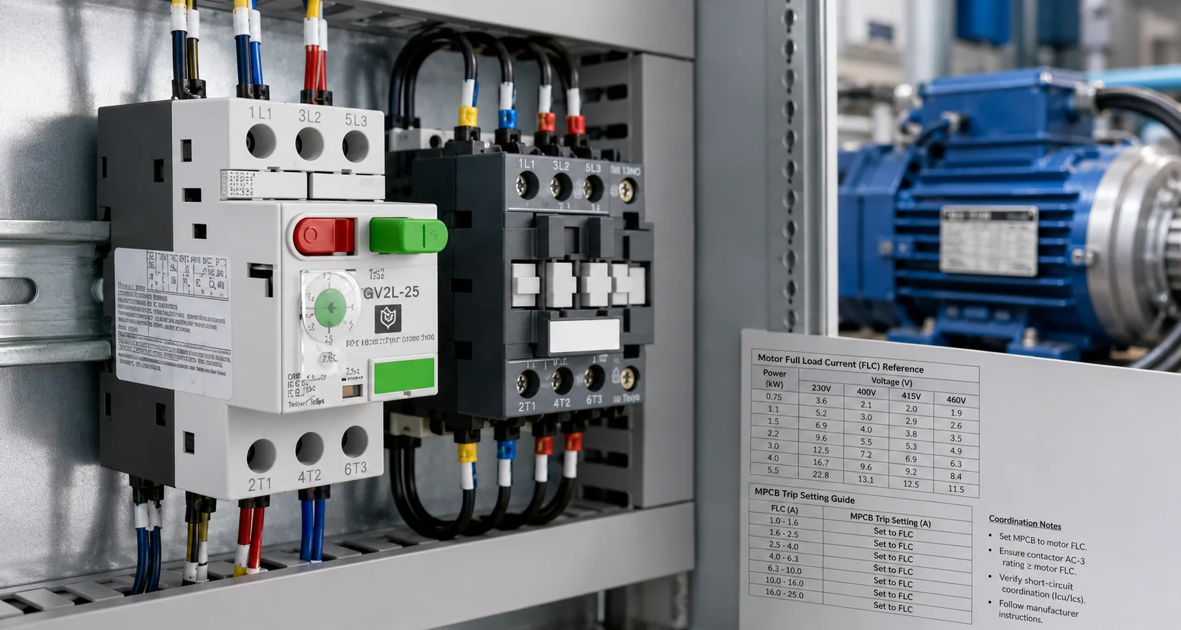
An MPCB should be set from the motor nameplate current, but the final setting is acceptable only when the motor can start without nuisance tripping and the complete feeder remains protected. The selected MPCB must coordinate with the contactor, motor cable and upstream short-circuit protective device. The setting should never be increased simply to hide a slow start, voltage drop or mechanical problem.
The practical task is to balance four requirements: carry normal motor current, tolerate legitimate starting current, respond to overload within the motor’s thermal limits, and safely clear or support clearing of a short circuit.
For the broader device-role comparison, read MPCB vs MCB vs Overload Relay for Motor Protection. For initial sizing and range selection, refer to How to Select an MPCB by Motor Current and Duty.
What must be coordinated in a motor feeder
MPCB coordination is not limited to one dial setting. The motor feeder includes the MPCB sensing elements, contactor power poles, control circuit, cable, motor and upstream protection. Each part has a separate job, and the feeder is safe only when those jobs work together.
|
Element |
Main responsibility |
Evidence to retain |
|
MPCB thermal element |
Protects the motor against sustained overcurrent |
Motor nameplate, selected setting and commissioning current |
|
MPCB magnetic response |
Responds to high fault current |
Trip curve, fault-current calculation and product data |
|
Contactor |
Carries and switches the motor duty | Exact product reference, utilization category and coordination table |
|
Motor cable |
Carries normal and starting current within its thermal limits |
Cable size, length, installation method and withstand check |
|
Upstream protection |
Provides selectivity or backup protection where required |
Manufacturer table or engineering study |
Thermal trip setting: begin with motor nameplate current
The adjustable thermal setting is intended for sustained overcurrent protection. The motor nameplate current at the intended supply voltage and connection is the correct starting point. A motor kilowatt value may support an estimate, but it does not replace the actual current marked on the motor.
Set the MPCB according to the motor data, duty, ambient conditions and manufacturer instructions. Do not raise the setting only because the motor trips during starting. That can mask a genuine problem and reduce overload protection.
Instantaneous response and motor start ride-through
The instantaneous magnetic function responds to high current. It must clear short circuits within the device capability, but it must also avoid operating during legitimate motor inrush. This makes the starting current, acceleration time and trip characteristic essential parts of the review.
A direct-on-line motor may draw several times its running current for a short period. A loaded conveyor, mixer or high-inertia fan may accelerate for longer. If the motor trips during starting, check the supply voltage, mechanical load, motor connection and start duration before changing the setting.
Contactor coordination: more than matching ampere ratings
The MPCB and contactor should be selected as a documented combination. Two devices with similar current ratings are not automatically coordinated. Their behaviour during a short circuit depends on the exact product references, contactor withstand and manufacturer-tested arrangement.
Use the current BCH MPCB range, contactor range and motor control catalogue when preparing the coordination schedule.
Type 1 and Type 2 coordination
Type 1 and Type 2 coordination describe the expected condition of a starter after a short circuit. Under Type 1 coordination, damage to the contactor or starter may be permitted as long as the fault does not create danger. The affected parts may require replacement before the circuit returns to service.
Type 2 coordination requires the starter to remain suitable for further service after the fault, although limited contact welding may be accepted where the manufacturer provides a safe separation method. The selected result must come from the exact tested device combination.
Upstream short-circuit protective device coordination
The upstream protective device may need to provide selectivity or backup protection. Selectivity aims to isolate only the affected motor feeder, while backup protection allows the upstream device to support the downstream device at higher fault levels.
Use manufacturer selectivity or backup tables where available. Where the proposed combination is not covered, an engineering study is required. Do not assume that a larger upstream breaker automatically provides correct coordination.
Commissioning procedure for MPCB settings
- Confirm the exact MPCB and contactor references against the approved coordination table.
- Verify motor voltage, connection, nameplate current and phase sequence.
- Set the MPCB with the supply isolated.
- Start the motor under representative operating conditions.
- Measure running current on all phases.
- Record starting time and investigate extended acceleration.
- Check phase imbalance and supply voltage during the start.
- Confirm that the selected setting matches the signed schedule.
- Record the final setting, measured values and reason for any approved deviation.
What repeated tripping may indicate
|
Trip pattern |
Possible areas to investigate |
|
Immediate trip at start |
Short circuit, locked rotor, incorrect motor connection, severe inrush or unsuitable magnetic response |
|
Trip after a few seconds |
Extended acceleration, low voltage, heavy load or inappropriate starting method |
|
Trip after several minutes |
Sustained overload, phase imbalance, poor ventilation or high ambient temperature |
|
Trip only when hot |
Thermal accumulation, repeated starts, resistive connection or enclosure heating |
|
Intermittent process-related trip |
Changing load, mechanical binding, product build-up or unstable supply |
Where a separate overload relay is used, the Overload Relay Setting Chart for Industrial Motors and Overload Relay Reset and Troubleshooting Guide provide related setting and diagnostic guidance.
Worked application example
Consider a mixer motor that occasionally starts under product load and has begun tripping after a process change. The motor nameplate and steady-state current have not changed, but the acceleration time is now longer.
The correct response is not to increase the MPCB setting immediately. First record the start current, start time, supply voltage and mechanical condition. If the new process load extends acceleration beyond the acceptable ride-through, the installation may require a process change, different starting method or revised motor-starter design.
After correcting the root cause, verify the thermal setting, instantaneous response, contactor coordination and upstream protection again. Save the measurements and final setting in the panel record.
Purchase specification checklist
- Motor rated current, voltage and connection
- Starting method and acceleration time
- Starts per hour and duty pattern
- MPCB adjustable current range
- Instantaneous or magnetic trip characteristic
- Applicable short-circuit rating
- Exact coordinated contactor reference
- Type 1 or Type 2 coordination requirement
- Upstream selectivity or backup requirement
- Required auxiliary contacts and accessories
- Ambient, enclosure and terminal conditions
- Trip curves, coordination tables and commissioning documents
Use the BCH download centre for current catalogues and submit project-specific motor and fault-level data through the BCH enquiry page.
Frequently asked questions
Why does an MPCB trip during motor starting?
Possible causes include excessive inrush, long acceleration, low voltage, mechanical loading, incorrect motor connection or an unsuitable trip characteristic.
Can I increase the MPCB setting to stop nuisance trips?
Not without investigating the cause. A higher setting may leave the motor under-protected.
Can two different brands be coordinated?
Only where documented test data or an approved engineering assessment supports the exact mixed combination.
What is the difference between Type 1 and Type 2 coordination?
Type 1 may allow starter damage after a short circuit, while Type 2 requires the starter to remain suitable for further service within the manufacturer’s stated conditions.
Should the MPCB setting equal the motor nameplate current?
The nameplate current is the starting point, but the final setting must follow product instructions, application duty and commissioning evidence.
Final takeaway
A correct MPCB trip setting protects the motor without interfering with legitimate starting and normal duty. A correct coordination study proves that the MPCB, contactor, cable and upstream protection will behave safely together during overload and short-circuit conditions.
Use the MPCB selection guide for initial sizing, the MPCB comparison guide for device-role clarification, and this guide for final trip-setting and coordination checks.
Setting records and change control
The final MPCB setting should appear on the approved drawing, feeder schedule or commissioning sheet. Record the motor reference, nameplate current, selected MPCB range, final dial setting, measured running current, starting time, ambient condition and the exact coordinated contactor reference. This creates a traceable baseline for future maintenance.
Any later adjustment should be treated as an engineering change rather than a routine field action. Note who approved the change, why it was necessary, what measurements supported it and whether the cable, contactor or upstream coordination was reviewed again. An undocumented setting change can make a later trip investigation difficult and may invalidate the original protection assumptions.
When the coordination study should be reviewed again
Review the trip setting and coordination after a motor replacement, process-load increase, change in starting method, transformer upgrade, cable change, panel relocation or repeated nuisance trips. These changes can alter starting current, fault level, voltage drop, thermal conditions or the duty seen by the contactor.
The review should also be repeated when a device is substituted because the original reference is unavailable. Matching the same current range is not enough. Confirm the new trip characteristic, breaking capacity, accessory compatibility and manufacturer coordination data before the replacement is accepted.
