
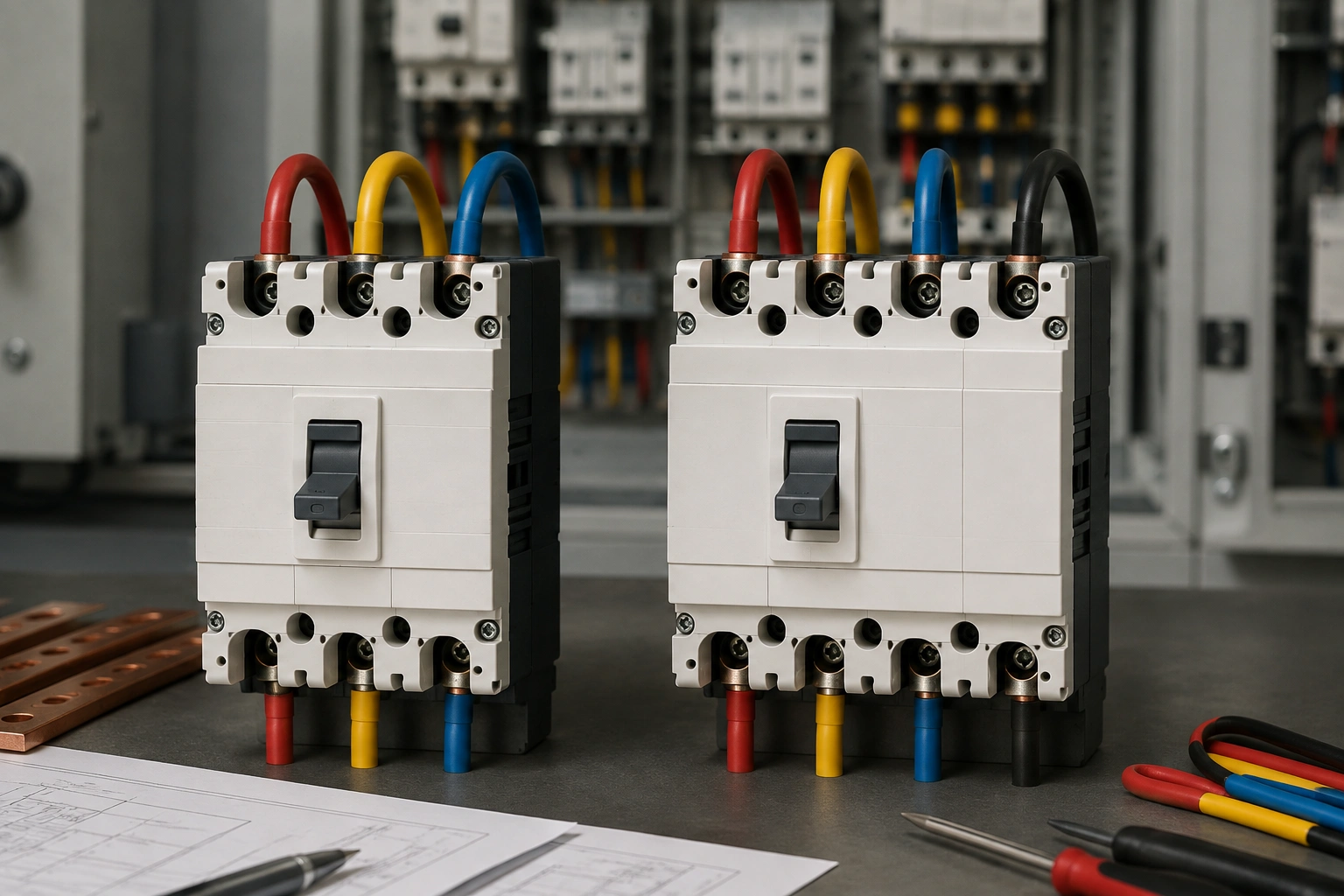
What is the difference between a 3-pole and 4-pole MCCB?
A 3-pole MCCB switches and protects the three phase conductors. A 4-pole MCCB also switches the neutral, but the neutral pole’s current rating, sensing arrangement and switching sequence depend on the exact device. The correct choice therefore comes from the earthing system, neutral isolation requirement, source-transfer arrangement, expected neutral current and project rules. It should not be selected simply because the circuit is three phase or because a four-pole device appears more complete. Begin with the current BCH MCCB range only after the system requirement has been defined.
|
Installation condition |
Design implication |
|
Three-wire load with no neutral |
A 3-pole MCCB is commonly considered, subject to the complete protection design. |
|
Four-wire feeder with required neutral isolation |
A 4-pole MCCB may be required. |
|
Generator or alternate-source transfer |
Review neutral switching, earthing and bonding as one system. |
|
High triplen harmonic content |
Calculate or measure neutral current before deciding conductor and pole requirements. |
|
Parallel sources or special earthing |
Use a formal protection and earthing review. |
Why the system neutral is the starting point
Pole selection begins with the single-line diagram and the role of the neutral in the installation. A three-phase motor feeder may not use a neutral at all. A mixed distribution board can supply many single-phase loads and therefore depend heavily on the neutral conductor. A source-transfer arrangement may require the neutral to be switched to preserve the intended earthing and bonding configuration.
The engineer should therefore identify where the neutral originates, where it is bonded, whether it is shared, what loads return through it and whether complete isolation is required. Only then does the choice between three and four poles become meaningful.
Does a 4-pole MCCB automatically protect the neutral?
No. The number of poles indicates that the neutral can be switched, but it does not automatically tell you whether the neutral is fully rated, whether it contains a current sensor, whether it has overcurrent protection or how it opens and closes relative to the phase poles. These are product-specific details.
Some applications require the neutral to close before the phase conductors and open after them; others require different treatment. The designer must check the exact MCCB documentation rather than infer the neutral behaviour from the phrase ‘4-pole’ alone.
When can neutral current become significant?
In a three-phase four-wire system, unequal single-phase loading creates neutral current. If one phase carries more single-phase load than the others, the vector sum no longer cancels completely and current returns through the neutral. This is common in commercial and institutional distribution boards where lighting, IT equipment and socket circuits are spread across phases.
Nonlinear electronic loads add another issue. Third-harmonic and other triplen harmonic currents can add in the neutral instead of cancelling. This means a board can show reasonably balanced phase currents while the neutral still carries substantial current. A neutral conductor or neutral pole should therefore not be reduced merely because the phase currents appear balanced at one moment.
How do harmonics influence 3-pole vs 4-pole selection?
Harmonics do not automatically mean a 4-pole MCCB is required, but they change the neutral-loading review. The load spectrum, phase allocation and expected operating pattern should be considered. Where electronic loads are dominant, measure or model neutral current and confirm that the conductor, busbar and MCCB neutral pole are suitable.
A breaker pole choice cannot compensate for an undersized neutral conductor or an overloaded neutral busbar. The complete path from source neutral to final circuits must be checked.
Why source-transfer systems need special attention
Generator-to-utility transfer, dual-source systems and some UPS arrangements can make neutral switching part of the earthing design. Whether the neutral remains solidly connected or is switched affects how the system is referenced to earth and how fault currents return. The transfer sequence can therefore be more important than the simple choice of three or four poles.
The approved single-line diagram should show the neutral arrangement clearly. Designers should avoid adding or omitting a neutral pole late in the project without reviewing the bonding and protection scheme.
What MCCB ratings still need to be selected after the pole count?
Pole count is only one parameter. BCH’s MCCB selection guide based on load and application is relevant because the breaker still has to protect the conductor, carry the intended demand and clear faults safely. The engineer must check current rating, trip-unit range, breaking capacity, operating voltage, terminal capacity, enclosure temperature and coordination with the rest of the distribution system.
- Rated operational current based on load and conductor design.
- Prospective short-circuit current at the installation point.
- Breaking-capacity requirement.
- Trip-unit type, range and settings.
- Neutral pole rating, sensing and protection details for four-pole devices.
- Selectivity or backup requirements with upstream and downstream protective devices.
- Terminal range, conductor size and enclosure thermal conditions.
- Switching and isolation role of the MCCB in the single-line diagram.
Why fault level matters independently of pole count
A 3-pole or 4-pole MCCB can still be unsuitable if its breaking capacity does not cover the available fault current. For installations with stronger supplies, large transformers or low-impedance feeders, use BCH’s high-fault-level MCCB selection guide as the related internal reference.
Fault level should be calculated or established at the actual board location. Using the transformer rating alone can be misleading because cable impedance and system configuration affect the prospective current. The selected MCCB must be suitable for the point where it is installed, not just for the nominal system voltage.
How should short-circuit coordination be reviewed?
Upstream and downstream protective devices should be reviewed together so that a downstream fault is cleared as locally as practicable and equipment remains within its limits. BCH’s short-circuit protection with MCCBs guide is the relevant cluster page for this part of the design.
Time-current curves, let-through energy and manufacturer selectivity or backup data may be needed. Pole count does not establish selectivity. A well-chosen four-pole breaker can still create unnecessary upstream trips if the protective settings are poorly coordinated.
A practical 3-pole vs 4-pole MCCB selection workflow
- Start with the approved single-line diagram and identify the source and earthing arrangement.
- Confirm whether the load is three-wire or four-wire.
- Identify whether the neutral must be isolated for maintenance, source transfer or another project requirement.
- List major single-phase loads and review expected phase imbalance.
- Identify nonlinear electronic loads and assess possible triplen harmonic contribution.
- Calculate or measure expected neutral current.
- Select the phase current rating and conductor protection requirement.
- Calculate the prospective short-circuit current and required breaking capacity.
- For a four-pole design, verify neutral rating, sensing, protection and switching sequence from the exact product data.
- Check upstream/downstream protection coordination and selectivity.
- Verify enclosure temperature, busbar rating, terminal capacity and board short-circuit rating.
- Record the final pole arrangement and its design basis on the single-line diagram and setting schedule.
Worked example: mixed-load commercial distribution board
Consider a three-phase four-wire distribution board serving office lighting, IT equipment, small power circuits and several electronic loads. The phase currents are approximately balanced at the main incomer, but measurement shows a meaningful neutral current. The board is also the local isolation point and the approved design requires the neutral to be isolated with the phase conductors.
A 4-pole MCCB may therefore be appropriate, but that decision is only the beginning. The engineer verifies the neutral pole rating and sensing, sizes the neutral conductor for the expected current and harmonics, calculates the fault level, selects the trip-unit range and checks coordination with downstream devices. The final design records why the neutral is switched and what product-specific neutral behaviour is required.
Worked example: three-phase motor feeder without a neutral
A dedicated three-phase motor feeder may use only the three phase conductors and protective earth, with no operational neutral. In that case, a 3-pole MCCB is commonly considered because there is no neutral conductor to switch. The breaker still has to be sized for the feeder, fault level and motor-starting conditions, and it must coordinate with the motor starter or downstream protective devices.
Installing a four-pole MCCB in such a circuit would not provide a meaningful neutral function because no neutral exists in the load path. This illustrates why pole count should follow the circuit topology rather than a preference for more poles.
Worked example: generator and utility transfer
In a system that can be supplied from either utility or generator, the neutral arrangement needs formal review. Depending on the earthing and bonding design, the neutral may need to be switched during source transfer. The engineer should confirm the required switching sequence, whether the neutral is solid or switched, and how each source is referenced to earth.
This is not a decision to make from an MCCB catalogue alone. The transfer equipment, source bonding, protective devices and neutral conductors form one system. The approved design should show the arrangement explicitly.
What should the purchase specification include?
A good MCCB specification should state the number of poles, rated current, operating voltage, trip-unit range, required breaking capacity, terminal requirements and any selectivity or backup requirement. For a four-pole MCCB, it should also state the required neutral current rating, sensing/protection arrangement and any switching-sequence requirement. Product selection should reference the exact BCH MCCB family and current power-control downloads.
Avoid vague wording such as ‘TPN MCCB suitable for panel’. The specification should explain whether the neutral is switched because of isolation, source transfer, earthing or another design requirement. That makes the choice reviewable and reduces the risk of an inappropriate substitution.
Installation and commissioning checks
- Confirm the installed pole arrangement matches the approved single-line diagram.
- Trace phase and neutral conductors and verify neutral routing.
- Check conductor cross-section, lugs/ferrules, strip length and terminal capacity.
- Verify the trip unit and settings against the signed setting schedule.
- Confirm protective-earth continuity and source/neutral bonding arrangement.
- For a four-pole device, confirm the exact neutral pole rating and switching behaviour from product documentation.
- Measure representative phase and neutral currents where the design depends on balance or harmonics.
- Record the final device reference, settings and measured values.
Common 3-pole vs 4-pole MCCB selection mistakes
- Choosing four poles simply because the board is three phase.
- Assuming a four-pole MCCB automatically protects or senses the neutral.
- Reducing neutral size without reviewing nonlinear loads and triplen harmonics.
- Ignoring the earthing and bonding consequences of switched-neutral source transfer.
- Selecting pole count before calculating fault level and breaking capacity.
- Assuming balanced phase currents always mean low neutral current.
- Changing the pole arrangement without updating the single-line diagram.
- Ignoring busbar, terminal and enclosure limits after selecting the breaker.
How should the design be reviewed when loads change?
Distribution systems evolve. Additional IT loads, LED lighting, variable-speed equipment or a new generator can change phase balance, neutral current, harmonic content and fault level. A pole arrangement that was reasonable when the board was commissioned may need to be reviewed after a major load change.
Do not preserve the old breaker arrangement solely because it has not tripped. Update the load schedule, measure representative phase and neutral currents, review the source configuration and re-check the MCCB rating and coordination.
Frequently Asked Questions
Does every TPN board need a 4-pole MCCB?
No. The correct pole arrangement depends on the board architecture, neutral use, incomer function, earthing system, isolation requirement and source-transfer design.
Can the neutral pole be smaller than the phase poles?
Only where the exact device, load profile and applicable rules permit it. Nonlinear loads can make neutral reduction inappropriate, so the expected neutral current should be calculated or measured.
Is a 4-pole MCCB always safer than a 3-pole MCCB?
No. Safety comes from selecting the correct architecture for the circuit and verifying the full protection design. An unnecessary neutral pole does not automatically improve protection.
Does a 4-pole MCCB always sense neutral current?
No. Neutral sensing and protection are product-specific. Check the exact MCCB documentation rather than assuming the fourth pole has the same sensing arrangement as the phase poles.
Where can BCH help with MCCB selection?
Share the single-line diagram, load, neutral requirement, fault level and source arrangement through the BCH enquiry page or use the BCH sales office directory for regional support.
Conclusion
The difference between a 3-pole and 4-pole MCCB is not simply the presence of an extra pole. The engineering decision is whether the neutral must be switched and how that neutral behaves in the real system. Earthing, isolation, source transfer, phase imbalance, harmonics, neutral current and product-specific sensing all influence the choice. Once the pole arrangement is defined, the MCCB still has to be selected for current, fault level, trip performance and coordination. A documented system review is therefore more reliable than choosing the breaker from phase count alone.
