
Quick answer
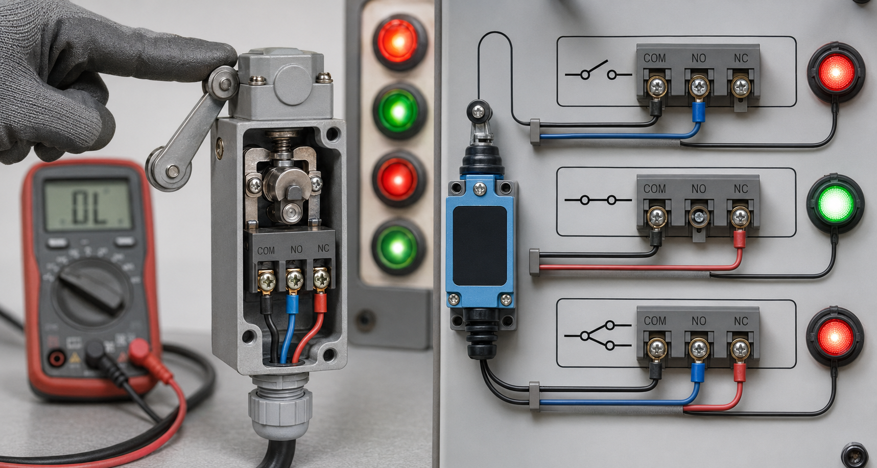
A limit switch can provide normally open (NO), normally closed (NC) or changeover contacts. In the normal, unoperated position, an NO contact is open and an NC contact is closed. A changeover contact has a common terminal that transfers from the NC terminal to the NO terminal when the actuator is operated. Correct wiring depends on the required control action, fault response and terminal markings shown on the product diagram.
Before wiring, confirm the exact contact arrangement and terminal identification on the selected BCH Electric limit switch. Do not rely only on a generic diagram because terminal numbering and the number of contact blocks can differ by model.
Why NO, NC and changeover contacts matter
A limit switch does not simply report “on” or “off.” Its contacts define what the control circuit sees before and after the machine reaches the operating point. That decision affects stopping logic, position confirmation, alarms, interlocks and fault detection.
For example, an NO contact can close when a gate reaches the fully open position and provide a positive confirmation signal. An NC contact can open when a carriage reaches the end of travel and remove the run command. A changeover contact can provide both states from one mechanically operated contact set: one path opens while the other closes.
The correct choice is not based on habit. It depends on what must happen during normal movement, what must happen after actuation and how the circuit should behave if a wire breaks or a terminal becomes loose.
Basic limit-switch contact terminology
|
Contact type |
Unoperated state | Operated state |
Typical use |
|
Normally open (NO) |
Open circuit | Closed circuit | Position achieved signal, cycle confirmation, alarm initiation |
| Normally closed (NC) | Closed circuit | Open circuit |
Stop command, permissive removal, fault-sensitive interlock |
|
Changeover (SPDT) |
Common connected to NC | Common transfers to NO | Simultaneous stop and indication, two-state feedback |
| Two independent contacts | Depends on model | Both change according to mechanism |
Separate control and indication circuits |
“Normal” means the actuator is not being operated. It does not mean that the machine is running, stopped, safe or unsafe. The machine designer must define those conditions separately.
How to identify COM, NO and NC terminals
Many changeover limit switches identify terminals as COM, NO and NC. Others use numerical terminal designations. The wiring diagram on the product, packaging or datasheet is the final reference. A continuity tester can help verify the contact states before installation, but testing must be performed with the circuit isolated and under an approved electrical safety procedure.
- COM or common is the moving contact connection in a changeover set.
- NC is connected to COM when the actuator is in the normal position.
- NO is disconnected from COM in the normal position and connects after actuation.
- With multiple contact blocks, each set may have separate common and switched terminals.
- Protective earth terminals, if provided, are not part of the switching contact set.
Example 1: NC contact used to stop forward travel
Consider a motor contactor coil that is energized through a forward command and an NC limit-switch contact. While the machine is within its permitted travel, the NC contact remains closed and the coil circuit can remain energized. When the moving cam operates the limit switch, the NC contact opens. The contactor coil de-energizes, removing the forward command from the motor circuit.
This is a common control principle, but the full design must include stopping distance, braking behavior, overload protection, emergency stopping and any required safety functions. The limit switch should not be expected to interrupt the motor power circuit unless the product is specifically rated and the design permits it.
For the power-switching element, review the relevant BCH Electric contactor products and verify coil voltage and utilization requirements.
Example 2: NO contact used for position confirmation
A conveyor gate may need to confirm that it has reached the fully closed position before the conveyor starts. The gate cam operates the limit switch, closing the NO contact. The PLC or relay then receives a “gate closed” input. If the contact does not close, the sequence remains blocked.
The target should operate the switch only when the mechanical condition is genuinely achieved. If the switch is mounted too early in the travel, the control system may receive confirmation before the gate is fully closed. Mechanical alignment is therefore part of wiring correctness.
Example 3: Changeover contact used for stop and indication
A changeover contact can open one circuit and close another at the same operating point. The NC path may be placed in the run-permissive circuit while the NO path feeds a position lamp or PLC input. When the switch operates, the run permissive is removed and the indication is activated.
This arrangement can reduce the number of separate sensing devices, but the contact ratings and circuit separation must be checked. Do not use one contact set for incompatible voltages or circuits unless the product design and applicable rules allow it.
Example 4: Two limit switches for forward and reverse travel
A reversible drive can use one limit switch at each end of travel. The forward-end limit opens the forward contactor control path while leaving reverse movement available. The reverse-end limit performs the opposite function. Electrical interlocking between the forward and reverse contactors remains necessary to prevent simultaneous energization.
The exact circuit may use contactor auxiliary contacts, relays, PLC logic or a combination of methods. Each end limit should be labelled clearly so that maintenance teams do not cross-connect the forward and reverse circuits during replacement.
Example 5: Hoist upper and lower limit logic
A hoist may have upper and lower limit switches. The upper switch should block further upward movement while allowing controlled downward movement. The lower switch should block further downward movement while allowing upward movement. The design must also consider final over-travel protection, brake response and the consequences of a failed contact or broken wire.
For a broader view of actuator selection, mounting, environmental duty and end-of-travel control in lifting and material-handling equipment, read Limit Switches for Cranes, Conveyors and Hoists: Application Guide. You can also review the BCH Electric Heavy Machinery Control application page for the wider machine-control context.
NO versus NC: which contact should you use?
There is no universal answer. The decision depends on the function and desired fault response. An NC circuit can lose continuity if the wire breaks, which may cause the control system to stop or report a fault. An NO circuit does not provide the same continuity monitoring in its normal open state, but it can be appropriate for positive position confirmation or indication.
|
Decision question |
NO may suit |
NC may suit |
|
What should happen before actuation? |
No signal or output is required |
A permissive circuit must remain complete |
|
What should happen after actuation? |
A confirmation or alarm signal should appear |
A run command or permissive should be removed |
|
How should a broken wire behave? |
May be indistinguishable from the normal open state unless monitored | Can interrupt the circuit and reveal loss of continuity |
|
Is two-state feedback required? |
Use with another contact or input |
Use changeover or multiple contacts |
For safety-related functions, contact choice is only one part of the architecture. Redundancy, monitoring, direct-opening action where required, control-system performance and applicable machine-safety requirements must also be reviewed by a qualified engineer.
Step-by-step wiring workflow
- Obtain the approved electrical drawing and the exact limit-switch datasheet.
- Confirm the control voltage, load type and contact rating.
- Identify the actuator’s normal mechanical position.
- Match COM, NO and NC terminals to the circuit function.
- Isolate all power sources and follow the site lockout procedure.
- Route conductors to avoid mechanical damage, heat and moving parts.
- Use suitable cable glands, ferrules and terminal torque.
- Check continuity in both unoperated and operated positions before energization.
- Verify the control response at reduced speed or under the approved commissioning method.
- Document terminal numbers, wire numbers and final operating point.
How a limit switch works with contactors, relays and PLC inputs
The limit switch normally handles a control signal. In a contactor circuit, its contact may be wired in series with the coil so that actuation interrupts the command. In a relay circuit, it can energize or de-energize an interposing relay. In a PLC system, the switch becomes a digital input and the software decides the response.
Each method has different electrical considerations. A contactor coil is an inductive load. A PLC input draws a small current and may have leakage or diagnostic behavior. Long cable runs can introduce voltage drop or noise. The product contact rating and the input characteristics should be checked together.
BCH Electric also provides foot switches for operator-actuated machine control. A foot switch and a limit switch may appear in the same machine, but they serve different purposes: one is intentionally operated by a person, while the other is operated by machine position.
Mechanical installation affects electrical behavior
Intermittent electrical signals are often caused by mechanical issues. If the cam only touches the edge of a roller, vibration can make the contact chatter. If the actuator is held exactly at the operating point, small movement can repeatedly open and close the circuit. The target should provide adequate, repeatable travel without forcing the actuator beyond its permissible range.
Cable routing also matters. Conductors should not pull on the terminal block or interfere with the mechanism. Cable entries must maintain the required enclosure protection. The switch should be mounted where technicians can test it without entering an unsafe machine zone.
Testing a limit-switch circuit
Testing should cover both contact continuity and machine response. With power isolated, verify which terminals are connected in the normal and operated positions. After the circuit is checked and the area is controlled, test the machine response according to the approved commissioning procedure.
- Confirm the correct direction is blocked when each end limit operates.
- Confirm the opposite direction remains available where the design requires it.
- Verify that indication lamps and PLC status agree with the physical switch position.
- Check for contact bounce or intermittent status during slow operation.
- Confirm the machine stops before reaching a mechanical end stop.
- Test wire-break or fault monitoring if included in the control design.
- Verify behavior after power loss and restoration.
Common wiring mistakes
- Assuming terminal numbering without checking the model diagram.
- Using NO where the design requires a closed permissive path.
- Using NC for indication without considering the meaning of a broken wire.
- Connecting a motor load directly through a control-rated switch.
- Exceeding the contact rating with a large or highly inductive coil.
- Mixing different control voltages on a contact set without verifying suitability.
- Cross-wiring forward and reverse end limits.
- Leaving spare conductors unidentified inside the enclosure.
- Testing electrical operation without checking actuator travel.
- Bypassing a limit switch during troubleshooting and failing to restore the circuit.
Selecting a BCH Electric limit switch for the circuit
After the contact logic is defined, compare the required actuator, number of contacts, contact arrangement, electrical rating, enclosure, mounting dimensions and environmental duty. BCH Electric’s sitemap provides several relevant product paths.
General-purpose limit switches can be reviewed for standard machine-position applications.
Precision limit switches may suit compact and repeatable detection requirements when their specifications match the machine.
Mini limit switches provide another path for space-constrained installations.
Heavy-duty NL Series limit switches should be evaluated for demanding mechanical and environmental duties.
Always use the current product documentation for terminal diagrams and ratings. The diagrams in a general article explain the logic, but they cannot replace the exact model wiring information.
Maintenance and troubleshooting guide
| Symptom | Possible causes | Checks |
| Input never changes | Wrong terminal pair, broken wire, actuator not reaching switch | Verify COM-NO/COM-NC continuity and mechanical travel |
| Input changes intermittently | Loose mounting, contact bounce, vibration, damaged cable | Inspect bracket, cam alignment, terminals and cable |
| Machine stops in wrong direction | Forward and reverse limits crossed or logic inverted | Trace wire numbers and compare with approved drawing |
| Contactor chatters near limit | Target holding actuator at transition point or unstable control voltage | Increase decisive travel and inspect control supply |
| Contacts fail early | Overload, inductive switching stress, excessive cycles or contamination | Check rating, load, suppression and environment |
Frequently asked questions
What is the difference between NO and NC in a limit switch?
NO is open when the actuator is not operated and closes after actuation. NC is closed in the normal position and opens after actuation.
What does changeover contact mean?
A changeover contact has one common terminal that connects to NC in the normal position and transfers to NO when the switch operates.
Can I identify NO and NC using a multimeter?
Yes, with the circuit safely isolated, continuity testing can confirm the normal and operated states. The product wiring diagram remains the primary reference.
Why is NC often used for stopping circuits?
An NC path can remove the command when the switch operates and can also open if continuity is lost. Whether that behavior is appropriate depends on the complete control and safety design.
Can a limit switch be connected directly to a PLC?
Often yes, if the contact type, input voltage, current, cable length and PLC input characteristics are compatible. Follow the product and PLC documentation.
Can one changeover contact operate a contactor and a PLC input?
It can provide separate NO and NC states, but circuit voltage, common reference, isolation and contact ratings must be reviewed. Do not combine incompatible circuits.
Where can I find the exact BCH Electric wiring diagram?
Use the current BCH Electric product page and product documentation for the selected model, or submit the application details through the enquiry page.
Final recommendation
Good limit-switch wiring starts with a clear definition of the required machine response. Choose NO for a signal that should appear after actuation, NC for a path that should open after actuation, and changeover when both states are needed from one operating point. Then verify terminal numbering, contact rating, actuator travel and the behavior of the complete control circuit.
Review the BCH Electric Limit Switches range and Detection & Sensing solutions. For model selection or application support, share the control voltage, load, contact requirement, actuator type and environment through the BCH Electric enquiry page.
