
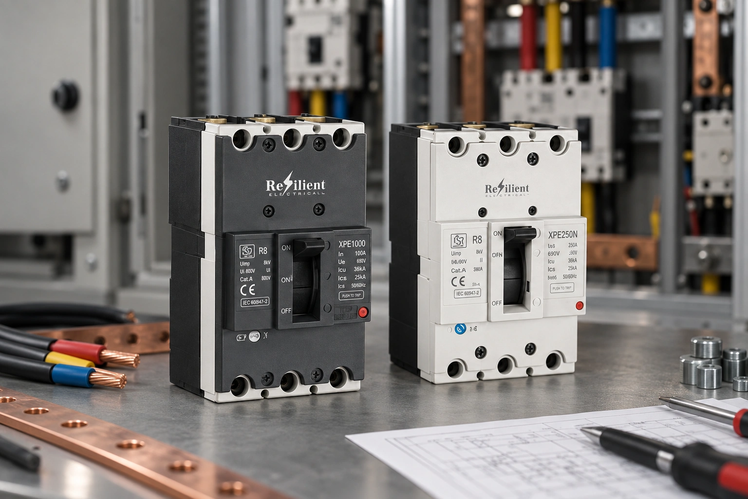
Selectivity and cascading solve different problems
Selectivity aims to keep a fault local by allowing the protective device closest to the fault to operate without unnecessarily opening an upstream device. Cascading, sometimes described as backup protection in manufacturer documentation, uses an upstream current-limiting device to support a downstream device under specified fault conditions. One is primarily about continuity of service; the other validates a tested protective combination. They should not be treated as synonyms.
|
Study |
Question to answer |
Evidence needed |
|
Selectivity |
Will the downstream device clear the fault without the upstream device opening? |
Manufacturer selectivity table and/or engineering curves |
|
Cascading |
Can the upstream device safely back up the downstream device at the stated fault level? |
Manufacturer-tested combination table |
Selectivity may be total up to a defined limit or partial up to a stated current. That limit belongs in the project schedule. A note that simply says “breakers coordinated” is too vague for design review or later maintenance because it does not identify the current range over which the coordination claim applies.
Start with fault current at each point in the system
Calculate prospective maximum and minimum fault current at the main bus and relevant downstream points. Record transformer or source data, conductor sizes and lengths, earthing arrangement and any generator or parallel-source contribution. The downstream fault level may be lower than the main bus value because of cable impedance, but it still has to be calculated rather than assumed.
Source changes can invalidate an old study. A larger transformer, parallel transformer, additional generator contribution or reduced conductor impedance can raise available fault current. Whenever the source or distribution arrangement changes materially, repeat the selectivity and cascading checks instead of carrying forward the previous conclusion.
Device identity and settings matter
Record the exact device family, frame size, rated current, trip unit and adjustable settings for both upstream and downstream breakers. Two MCCBs with similar current markings can have different time-current behaviour and different published coordination data. The study must be tied to exact references, not generic labels such as “250 A MCCB.”
For product-level reference, use the published information for the BCH MCCB family and the broader BCH power control range. Final coordination decisions should still rely on the exact manufacturer tables for the selected devices.
How to review selectivity
Begin in the overload region and work toward higher fault currents. Compare time-current characteristics and confirm that the downstream device acts first over the required range. Adjustable long-time, short-time and instantaneous functions can affect the result, so settings should be part of the study rather than added later during commissioning.
At high fault currents, simple curve overlays may not tell the whole story because current-limiting behaviour and energy let-through can influence the interaction. That is why manufacturer selectivity tables are important. If the table states a selectivity limit, record that value explicitly and make sure the calculated fault current at the downstream point is understood relative to it.
How to review cascading
Cascading is based on a tested combination. The upstream device may limit the fault energy seen by the downstream device, allowing the combination to be used at a stated conditional short-circuit level. That does not change the downstream breaker’s standalone marking; it means the particular upstream/downstream pair has verified performance when used together as specified.
Do not create a cascading claim by comparing breaking capacities or by assuming that a larger upstream breaker will protect any smaller downstream breaker. Use the published combination table and respect the stated device families, ratings, settings and conditions. If the proposed pair is not listed, obtain application guidance rather than extending the table by analogy.
A practical study sequence
- Define which loads or boards require continuity of service.
- Calculate maximum and minimum fault current at the relevant buses and feeders.
- Select downstream protection for the cable, load and local fault level.
- Select and set the upstream device for feeder and system protection.
- Check overload and short-circuit selectivity using curves and manufacturer data.
- Check cascading only with published compatible combinations.
- Confirm conductor withstand, assembly short-circuit rating and busbar capability.
- Record device references, settings, selectivity limit, cascading evidence and revision date.
Do not forget the assembly around the MCCBs
Protection studies are often drawn as simple breaker symbols, but the installed assembly also matters. Verify busbar rating, neutral arrangement, enclosure temperature, incoming and outgoing terminal capacity and the switchboard short-circuit rating. Spare ways do not prove that the board has enough thermal or short-circuit capacity for a future large load.
Boards supplying many single-phase electronic loads may also require attention to neutral loading, harmonics and phase allocation. These issues do not replace the short-circuit study, but they influence conductor and pole selection and can affect how the distribution system should be documented.
If the project is deciding whether the neutral should be switched, BCH’s 3-pole vs 4-pole MCCB guide is a more relevant reference than forcing that discussion into a selectivity calculation. The pole decision and the coordination study should remain related but distinct.
Commissioning: settings must match the study
Before energisation, compare installed breaker references and trip-unit settings with the approved study. A selectivity result based on one instantaneous or short-time setting may no longer apply if the field setting is changed. Adjustable values should therefore be captured on the drawing or setting schedule and verified during commissioning.
Inspect conductor sizes, terminal preparation and tightening requirements, protective-earth continuity and the physical condition of the assembly. Energised testing should be planned by competent personnel. Where measurements are taken, record actual phase voltage and load current rather than relying only on nominal values.
What repeated trips can reveal
When a breaker operates, first identify which device tripped and which trip function was involved. An immediate short-circuit operation points to a different investigation from a long-time overload trip after sustained demand. If both upstream and downstream breakers open for a downstream event, compare the actual fault condition and settings with the selectivity study before changing either device.
Do not solve an unexplained trip by simply increasing a rating or delaying a protective function. The fault level, load growth, conductor condition, settings or device substitution may have changed. Preserve the event evidence, then test one hypothesis at a time.
What belongs in the project record
- Maximum and minimum fault current at each relevant board
- Upstream and downstream MCCB exact references
- Trip-unit type and final settings
- Selectivity limit and supporting table/curve reference
- Cascading combination and conditional rating where applicable
- Cable short-circuit withstand and conductor data
- Assembly/busbar short-circuit rating
- Study revision date and assumptions
This record is what makes the design auditable years later. It allows a maintenance engineer to check whether a replacement breaker or revised setting still fits the original coordination intent instead of assuming that a similar current rating is equivalent.
For current product literature supporting the equipment-selection stage, the BCH power control downloads can be used alongside the project fault-current study and manufacturer coordination tables.
Prioritise continuity where it actually matters
Not every branch of a distribution system needs the same degree of selectivity. A process line, life-safety auxiliary supply or critical control board may justify a stronger continuity objective than a non-critical workshop feeder. Define those priorities before adjusting breaker settings, because unnecessary delay in an upstream protective device can conflict with other protection requirements.
The study should therefore state where selective operation is essential and where a limited selectivity level is acceptable. That makes the result useful to operations teams: they can see which downstream faults are intended to remain local and which events may legitimately remove a larger part of the system.
Minimum fault current matters too
Maximum prospective fault current is central to breaking capacity and cascading, but minimum fault current also deserves attention. At the remote end of a long feeder, fault current can be lower than expected. Protective settings must still provide the required fault detection and clearing performance under those conditions.
Checking both ends of the fault-current range prevents a study from focusing only on the dramatic high-current case. The final design needs sufficient capability at the maximum level and dependable operation at the lower levels that can occur at remote points in the installation.
Control substitutions after commissioning
Breaker replacement is a common point where coordination is lost. A device with the same current rating and a similar frame size may have a different instantaneous threshold, trip-unit curve or current-limiting characteristic. If the original selectivity or cascading evidence names an exact family, the replacement should be checked against that evidence before installation.
The same applies to setting changes made to solve nuisance trips or accommodate load growth. Any change to long-time, short-time or instantaneous settings can alter the coordination result. Update the study and setting schedule so the as-built system remains traceable.
FAQs
Does a higher-rated upstream MCCB guarantee selectivity?
No. Instantaneous and short-time operating regions can overlap even when frame sizes differ. Use the exact device curves and manufacturer selectivity tables.
Is selectivity always all-or-nothing?
No. A manufacturer may state total selectivity for a combination or partial selectivity up to a defined current. Record the applicable limit in the schedule.
Can cascading increase the downstream breaker rating?
It can provide a stated conditional short-circuit capability as part of a tested upstream/downstream combination. It does not change the downstream breaker’s standalone marking.
Why are manufacturer tables needed if I already have time-current curves?
Curves are essential, but high-fault current-limiting behaviour and energy interaction may not be fully represented by a simple overlay. Manufacturer tables capture tested combinations and stated limits.
When should an MCCB coordination study be repeated?
Repeat it after material changes such as a larger or parallel transformer, added generation, altered feeder impedance, device substitution, changed trip settings or a major load/distribution reconfiguration.
What should be checked when replacing an MCCB?
Confirm the exact family, frame, trip unit, rating, settings, breaking capacity and its place in the existing selectivity or cascading study. Similar ampere ratings are not enough.
