
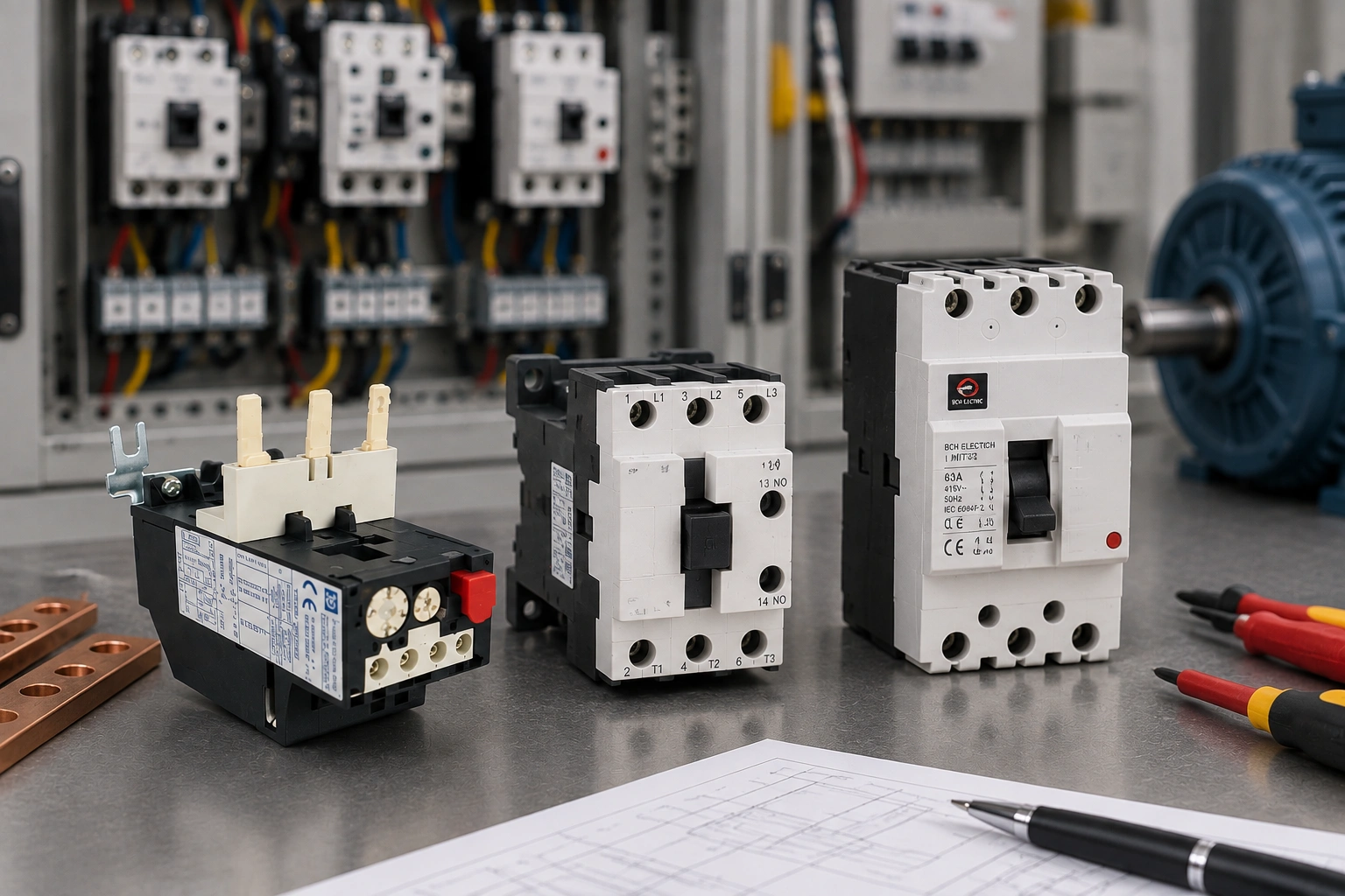
A coordinated starter is a system, not three ratings
An overload relay, contactor and short-circuit protective device (SCPD) do different jobs in a motor starter. The overload relay responds to sustained overcurrent and commands the contactor to open. The contactor carries and switches the motor under its intended utilisation category. The SCPD clears short-circuit current. A reliable starter depends on how those three devices behave together under normal running, starting, overload and fault conditions.
That distinction matters because a component can be individually suitable and still be unsuitable in the assembled starter. An AC-1 contactor rating, for example, does not prove AC-3 motor duty. In the same way, a breaker or fuse with adequate breaking capacity does not automatically establish the coordination performance of the starter combination.
For a related explanation of what happens to the starter after a short circuit, see BCH’s Type 1 vs Type 2 motor starter coordination guide. That distinction is useful when the project specification calls for a particular post-fault condition.
Give each device a clearly defined duty
| Component | Primary selection basis | What to verify |
| Contactor | Utilisation category, operational current, voltage, switching duty | Motor duty and exact coordination combination |
| Overload relay | Motor current range, trip class, phase sensitivity, reset method | Setting, acceleration tolerance and thermal behaviour |
| SCPD | Prospective fault current, cable protection, device type | Breaking capacity and manufacturer coordination table |
The overlap between these functions is where selection errors usually occur. The overload relay is not intended to interrupt high short-circuit energy by itself. The contactor is not a protective device. The SCPD should not be oversized simply to avoid nuisance operation during starting. Each device must cover its own assigned function while remaining compatible with the rest of the starter.
Start with motor and installation data
Begin with the motor nameplate and the driven load, not with a catalogue number. Record rated voltage, connection, full-load current, starting method, acceleration time, starts per hour and the load torque pattern. These inputs define the temporary current the starter must tolerate and the sustained conditions the overload relay must detect.
Then look at the installation. A long cable or weak feeder can reduce motor terminal voltage during starting, increasing acceleration time. High ambient temperature, closely packed components and poor enclosure ventilation raise thermal stress. Repeated starts can heat the motor and starter even when each individual start appears normal. Mechanical problems can also lengthen acceleration and make a correctly set overload relay trip.
When selecting the switching device itself, use the published data for the exact BCH contactor family and application. For the overload function, review the available BCH overload relay range rather than assuming that matching ampere markings prove compatibility.
A practical coordination sequence
- Record the motor nameplate, starting method, acceleration time and operating duty.
- Select the contactor at the correct utilisation category and operational voltage.
- Choose an overload relay range that contains the motor rated current and allows a practical setting.
- Match the trip class to the real acceleration time and motor thermal capability.
- Calculate the prospective short-circuit current at the starter location.
- Select the exact SCPD from published manufacturer Type 1 or Type 2 coordination data.
- Confirm conductor protection, enclosure temperature, control voltage and terminal capacity.
- Record the exact device references, settings and evidence as one approved starter combination.
This sequence prevents a common shortcut: choosing the contactor from motor kilowatts, the overload relay from full-load current and the breaker from a convenient standard rating, then assuming the three selections form a coordinated starter. They may not. The coordination table is evidence for an exact combination, not a broad endorsement of any devices with similar current ratings.
Trip class must fit the real acceleration
The overload relay must allow legitimate starting current long enough for the motor to accelerate, while still protecting against a sustained overload. A trip class that is too fast can cause unwanted trips on a healthy high-inertia load. A trip class that is too slow can reduce the protection margin when the motor stalls or runs overloaded. Use the actual start time, motor thermal information and the relay’s published characteristics to make the decision.
If trips appear only after several successful starts, treat that pattern as useful evidence. Accumulated heat, reduced cooling time, low voltage or an increasing mechanical load can move the motor and starter beyond their thermal capacity. Increasing the relay setting without finding the cause may hide the symptom while reducing protection.
Fault level and Type 1 or Type 2 coordination
Prospective short-circuit current must be calculated at the point where the starter is installed. The SCPD then needs adequate capability for that fault level and must be the device specified in the manufacturer’s coordination data. A breaker with a higher standalone breaking capacity is not automatically an acceptable substitute because the tested interaction with the contactor and overload relay may be different.
Type 1 and Type 2 coordination describe different acceptable conditions after a short circuit. The project should state which outcome is required and identify the exact tested combination used to achieve it. If the published data does not cover the proposed references, setting or fault level, obtain written application guidance instead of inferring equivalence.
Installation details can undo a good selection
Once the devices are selected, check conductor material and cross-section, strip length, ferrules or lugs, terminal capacity and tightening torque. Maintain the clearances and ventilation stated for the products. Keep control wiring arranged so that electrical noise or accidental contact with power wiring does not compromise the control circuit. In compact panels, heat from nearby devices can make catalogue ambient assumptions unrealistic.
Before energisation, compare the assembly with the approved drawing. Confirm the contactor, overload relay and SCPD references, coil or control voltage, pole arrangement, auxiliary contacts and protective-earth continuity. Adjustable settings should match the signed setting schedule. Interlocks and trip contacts should be functionally tested before the starter is put into service.
Commission using measured values
A commissioning record should contain more than “checked OK.” Measure phase voltage and current under a representative operating condition. For a motor starter, capture the start as well as steady operation when practical and safe. If phase imbalance is relevant, record the phases separately. Note the ambient condition and any unusual process state that could affect the result.
If a protective device operates, identify exactly which element acted before resetting it. An overload indication points to a different investigation from an SCPD trip or a control-circuit dropout. Timing also helps: an immediate trip, a trip during acceleration and a trip after ten minutes are different fault patterns. Make one evidence-led change at a time so the cause remains traceable.
What to put in the purchase specification
Describe the application before naming a preferred reference. State the supply voltage and frequency, motor current, starting method, duty, starts per hour, expected fault level, ambient conditions and required coordination type. Then require the supplier or panel builder to declare the exact contactor, overload relay and SCPD references, together with the published coordination evidence.
For a broader view of compatible switching and protection families, the BCH motor control products section is a useful next step. It should complement, not replace, the exact coordination tables used for the final selection.
Design record checklist
- Motor rated current and starting data
- Contactor utilisation category and operational rating
- Overload relay range, setting and trip class
- Prospective short-circuit current at the starter
- SCPD type and exact reference
- Required Type 1 or Type 2 coordination
- Control voltage, wiring and enclosure conditions
- Catalogue/table reference and revision date
Keeping these details on the drawing or setting schedule makes later maintenance safer. A service engineer can distinguish the approved design from an undocumented field change, and any substitution can be checked against the same design basis.
Substitution control is part of coordination
A coordinated starter should be treated as a documented combination, not a collection of interchangeable parts. If a contactor, overload relay or SCPD becomes unavailable, check the proposed replacement against the same motor duty, fault level and manufacturer coordination evidence used for the original design. A physically compatible replacement can still have different current-limiting behaviour, trip characteristics, coil requirements or thermal performance.
The same rule applies to field changes. If maintenance increases an overload setting, replaces a breaker with another family or changes a contactor frame, update the approved record and repeat the affected checks. This keeps the protection intent visible and prevents a gradual drift from a tested starter combination to an undocumented assembly that only appears equivalent.
Use fault evidence to improve the design
After a genuine fault or repeated trip, preserve the evidence before changing settings. Record which device operated, the process state, motor current if available, ambient condition and how long the motor had been running. A starter that trips only during hot restarts points to a different cause from one that trips instantly on the first start of the day.
Good records also help identify whether the problem belongs to protection, switching, supply quality or the mechanical load. That distinction avoids the common cycle of replacing devices without fixing the underlying condition and gives the next engineer a clear basis for comparison.
FAQs
Should the overload relay range match the contactor size?
Mechanical compatibility matters, but the relay must primarily suit the motor current, required trip behaviour and the tested starter combination. Similar frame sizes alone do not prove correct coordination.
Can I increase the overload setting to stop nuisance trips?
Only after finding the reason for the trip. Low voltage, long acceleration, frequent starting, high ambient temperature or a mechanical problem can all increase thermal stress. Raising the setting without evidence can reduce motor protection.
What happens if the contactor is oversized?
It may carry the motor current, but the coordination evidence, coil consumption, panel space and economics can change. Confirm the exact combination rather than assuming a larger contactor is automatically better.
Does a higher-breaking-capacity breaker guarantee starter coordination?
No. Breaking capacity is only one requirement. Type 1 or Type 2 coordination depends on the tested behaviour of the exact SCPD, contactor and overload relay combination.
How should trip class be selected?
Use the actual acceleration time, load duty, motor thermal capability and the relay manufacturer’s trip characteristics. The objective is to tolerate a legitimate start without allowing a damaging sustained overload.
When should coordination be reviewed again?
Review it after a motor change, transformer or supply change, higher fault level, altered starting method, repeated nuisance trips, major enclosure changes or substitution of any device in the coordinated combination.
