
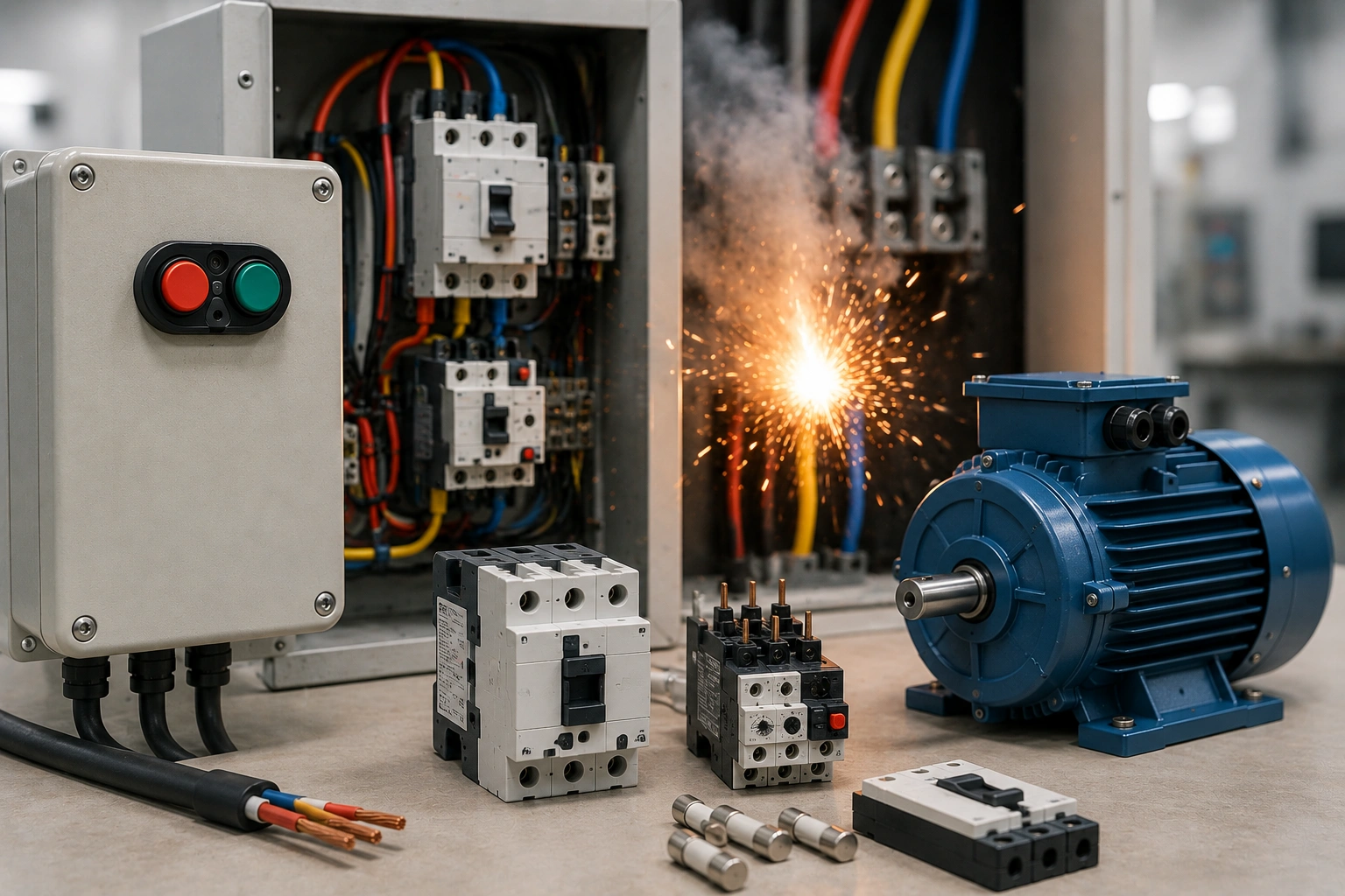
What is the difference between Type 1 and Type 2 motor starter coordination?
Type 1 and Type 2 coordination define the acceptable condition of a motor starter after a short circuit. In the IEC 60947-4-1 framework referenced in the supplied draft, Type 1 coordination permits the contactor or starter to require repair or replacement after the fault, provided the event does not create danger. Type 2 coordination requires the equipment to remain suitable for further service after the prescribed checks, although limited contact welding can be acceptable under the standard’s conditions. The important point is that coordination is not a label attached to one contactor or one breaker. It belongs to the complete tested combination of the switching device, overload function, short-circuit protective device, operating voltage and fault level. For BCH applications, begin with the motor starter range and then verify the exact combination against current coordination data.
|
Factor |
Type 1 |
Type 2 |
|
Post-fault condition |
Repair or replacement of starter components may be required |
Starter is intended to remain suitable for further service after the required checks |
|
Permitted damage |
Damage may occur within the standard’s safety outcome |
No significant damage; limited contact welding may be allowed under stated conditions |
|
Expected downtime |
Potentially higher because replacement may be needed |
Potentially lower where the tested combination performs as specified |
|
Selection evidence |
Manufacturer coordination/test table |
Manufacturer coordination/test table |
|
Typical decision driver |
Economy where post-fault replacement is acceptable |
Continuity where rapid return to service is valuable |
Why motor starter coordination matters beyond fault clearing
Short-circuit protection is often discussed as if the only objective were to interrupt fault current. That is only part of the engineering decision. A motor branch also has to start the motor without nuisance operation, carry the normal load, tolerate the expected duty cycle, protect the conductors and respond correctly to overloads or phase problems. Coordination adds another question: what condition should the starter be in after a severe short circuit has been safely cleared? The answer affects maintenance planning, spare-part strategy, production restart and the evidence that must be kept with the panel.
This is especially important in industrial systems where two starters with similar current ratings can have very different tested coordination results when paired with different short-circuit protective devices. A substitution made during maintenance can therefore change the coordination outcome even when the replacement contactor appears electrically similar. The approved combination should be treated as part of the protection design, not merely as a bill-of-material preference.
What equipment belongs inside the coordination boundary?
The starter should be reviewed as a system. BCH’s guide explaining how motor starters work with contactors and overload relays is relevant because the switching and overload functions are intentionally different. During a short-circuit coordination review, the system boundary normally includes the contactor or switching device, overload relay or equivalent overload function, short-circuit protective device, motor branch conductors, operating voltage, enclosure conditions and the prospective short-circuit current at the installed point.
- Motor nameplate voltage, current, starting method and operating duty.
- Contactor reference and utilisation category appropriate to the motor switching duty.
- Overload relay or overload-protection reference and setting range.
- Short-circuit protective device type, rating and exact reference.
- Prospective short-circuit current at the starter panel.
- Conductor size and short-circuit withstand.
- Enclosure temperature, ventilation and terminal conditions.
- Required Type 1 or Type 2 post-fault outcome and inspection procedure.
Why a larger contactor does not automatically give Type 2 coordination
Type 2 coordination cannot be created simply by installing a larger contactor or choosing a protective device that trips faster. The complete device combination has to match published test evidence for the required voltage and fault level. BCH’s contactor selection guide helps with the normal operating-duty side of the decision, while the guide to AC-1, AC-3 and AC-4 contactor ratings explains why switching duty matters independently of short-circuit coordination.
A larger device can also create new problems if it falls outside the tested combination, changes coil/control characteristics, requires different terminals or no longer matches the overload relay range. Coordination is therefore a verification exercise, not an oversizing exercise. The correct question is not ‘Which contactor is strongest?’ but ‘Which exact combination has evidence for the motor duty, voltage and prospective fault current in this installation?’
How do the SCPD, contactor and overload relay divide the protection job?
The contactor performs repeated switching. The overload function responds to sustained motor overcurrent according to its characteristic. The short-circuit protective device clears much higher fault current. None of these functions should be assumed to replace the others unless the selected product architecture specifically combines them.
Where an MPCB forms part of the branch, BCH’s MPCB trip settings and contactor coordination guide is a useful companion because motor current settings and contactor coordination must be checked together. A motor protective device may simplify the architecture, but the project still needs evidence that the final combination meets the required coordination outcome.
How should you decide whether Type 1 or Type 2 is appropriate?
|
Question |
Why it affects the decision |
|
How costly is downtime? |
High downtime cost can make a Type 2 outcome more valuable. |
| Can the process tolerate replacement after a fault? |
If yes, Type 1 may be an acceptable and economical design choice. |
|
What fault level is available? |
The tested combination must cover the actual prospective short-circuit current. |
| Are spare starters or contactors held on site? |
Spares reduce recovery time for Type 1 applications. |
|
Is the driven equipment critical to safety or production? |
Criticality affects restart expectations and maintenance planning. |
| Is an exact tested combination available? |
A coordination claim should be supported by current manufacturer data. |
Type 2 is often attractive because it can reduce recovery time after a fault, but it should not be presented as universally mandatory or universally superior. The required outcome comes from the project specification, risk assessment, continuity requirement and applicable rules. In a low-criticality auxiliary circuit, Type 1 may be entirely reasonable if safe fault clearing is assured and replacement after the event is acceptable. In a production bottleneck, the economics can point the other way.
What information should be collected before selecting the starter combination?
- Record the motor rated voltage, nameplate current, connection and starting method.
- Record acceleration time, starts per hour and any jogging, inching or reversing duty.
- Measure or calculate the prospective short-circuit current at the starter location.
- Confirm the conductor size, installation method and short-circuit withstand.
- Define whether Type 1 or Type 2 coordination is required.
- Shortlist the starter architecture using the current BCH motor starter portfolio.
- Identify the exact contactor, overload device and SCPD references.
- Check the manufacturer’s coordination table at the required voltage and fault level.
- Review enclosure temperature, ventilation, cable entry and terminal capacity.
- Define the post-fault inspection, spares and return-to-service process.
- Save the coordination table, calculation basis and final settings with the panel record.
How does motor duty affect coordination selection?
The short-circuit coordination table does not remove the need to select the contactor for normal motor duty. A pump with occasional starts, a conveyor that starts frequently and a machine that uses plugging or reversing can impose very different switching stress. If the contactor is unsuitable for normal duty, a valid short-circuit coordination combination will not correct that underlying application error.
Starting time also matters. A mechanically overloaded machine, weak supply or long cable can extend acceleration and keep current elevated for longer than expected. That can cause overload operation or contactor heating and may be wrongly interpreted as a coordination problem. Before changing a protective device or starter size, confirm that the motor reaches speed normally under representative load.
What should the purchase specification include?
A practical purchase specification should state the required coordination type, operating voltage, prospective short-circuit current, motor current or starter rating, utilisation category where relevant, exact device references and required coordination evidence. It should also state whether post-fault inspection instructions, spare contact kits or replacement devices are required at handover.
Use BCH’s current motor starter download section when finalising the range and product documentation. The specification should avoid vague phrases such as ‘heavy duty’, ‘best quality’ or ‘Type 2 suitable’ unless the exact tested combination and conditions are identified.
Worked example: production conveyor with a high downtime cost
Consider a conveyor motor that feeds a packaging line. The motor starts several times per shift, and a prolonged shutdown stops downstream production. The engineer records the motor current, operating voltage and starts per hour, then calculates the prospective short-circuit current at the starter panel. The project requires a rapid return to service after a cleared fault, so Type 2 coordination is specified.
The next step is not to choose an oversized contactor. The engineer identifies an exact starter combination covered by the manufacturer’s coordination data at the required voltage and fault level. The overload range covers the motor nameplate current, and the contactor is suitable for the normal switching duty. The selected SCPD is the one stated in the coordination evidence. During commissioning, the device references and settings are recorded so that a future maintenance replacement does not accidentally invalidate the tested combination.
Worked example: noncritical auxiliary motor
Now consider a small ventilation motor that serves a noncritical area. The process can tolerate a longer restart after a rare short-circuit event, and a spare contactor is held on site. If the risk assessment and applicable design rules permit it, Type 1 coordination may provide an acceptable balance of safety and cost. The important point is that Type 1 still requires an approved combination and safe fault clearing; it is not a lower-quality or uncontrolled design.
What should be inspected after a short circuit?
- Identify and correct the original fault before re-energising.
- Follow the manufacturer’s post-fault inspection procedure for the coordination type.
- Inspect contactor contacts and mechanical operation for damage or welding as required.
- Check the overload function, SCPD and associated terminals.
- Inspect conductors, lugs, insulation and enclosure for thermal or mechanical damage.
- Confirm device references have not been substituted.
- Record what was inspected, replaced or reset and why.
Type 2 coordination does not mean ‘no inspection required’. The circuit experienced a genuine fault, and the cause must be understood before the system returns to service. Similarly, Type 1 should not be treated as permission to replace the contactor blindly without checking cables, terminals, the motor and the short-circuit protective device.
Common mistakes in Type 1 and Type 2 coordination
- Selecting a coordination type without calculating the actual fault level.
- Assuming a larger contactor automatically improves the coordination class.
- Substituting the SCPD, overload relay or contactor with a similar current rating.
- Using a coordination table for the wrong operating voltage.
- Ignoring normal utilisation category and switching duty.
- Failing to retain the tested combination reference in panel documentation.
- Treating Type 2 as a guarantee of immediate restart without inspection.
- Changing overload or protection settings to solve a mechanical starting problem.
How should coordination information be maintained over the life of the panel?
The panel record should include the coordination type, tested combination reference, prospective short-circuit current, final overload setting, contactor and SCPD references, operating voltage and post-fault instructions. This makes future maintenance auditable. If the transformer changes, the supply network is strengthened, the motor is replaced or a starter component is substituted, the coordination check should be repeated because the original assumptions may no longer be valid.
Maintenance teams should also record fault history. Repeated starter replacement after short circuits can indicate an upstream system issue, cable damage, motor insulation problem or process condition that deserves investigation rather than repeated component replacement.
Frequently Asked Questions
Is Type 2 coordination always mandatory?
No. The appropriate coordination type depends on the project specification, risk assessment, continuity requirement, downtime consequence and applicable rules. Type 1 can be a valid choice where replacement after a fault is acceptable.
Does Type 2 mean the starter will never need replacement?
No. Type 2 describes the required post-fault outcome under the applicable test conditions. Actual equipment must still be inspected after a fault and can require service if the real event or installation condition exceeds those assumptions.
Can I use a different brand or model with the same current rating?
Not automatically. The coordination claim belongs to the tested combination. A substitute should be supported by equivalent manufacturer coordination evidence for the same operating conditions.
Is the overload relay the short-circuit protective device?
No. The overload function addresses sustained motor overcurrent. Short-circuit protection is a separate function unless the chosen product architecture specifically integrates both.
Where can I get BCH support for a starter application?
Share the motor rating, supply voltage, fault level, operating duty and required coordination outcome through the BCH enquiry page or use the BCH sales office directory for regional support.
Conclusion
The difference between Type 1 and Type 2 motor starter coordination is ultimately a difference in the required post-short-circuit condition of the starter. Type 1 may require repair or replacement; Type 2 is intended to remain suitable for further service after the prescribed checks. Neither outcome should be selected from a marketing label or an individual component rating. The reliable method is to define the fault level and continuity requirement, choose the exact tested starter combination, verify normal motor duty, document the evidence and preserve that information for future maintenance.
