
Quick answer
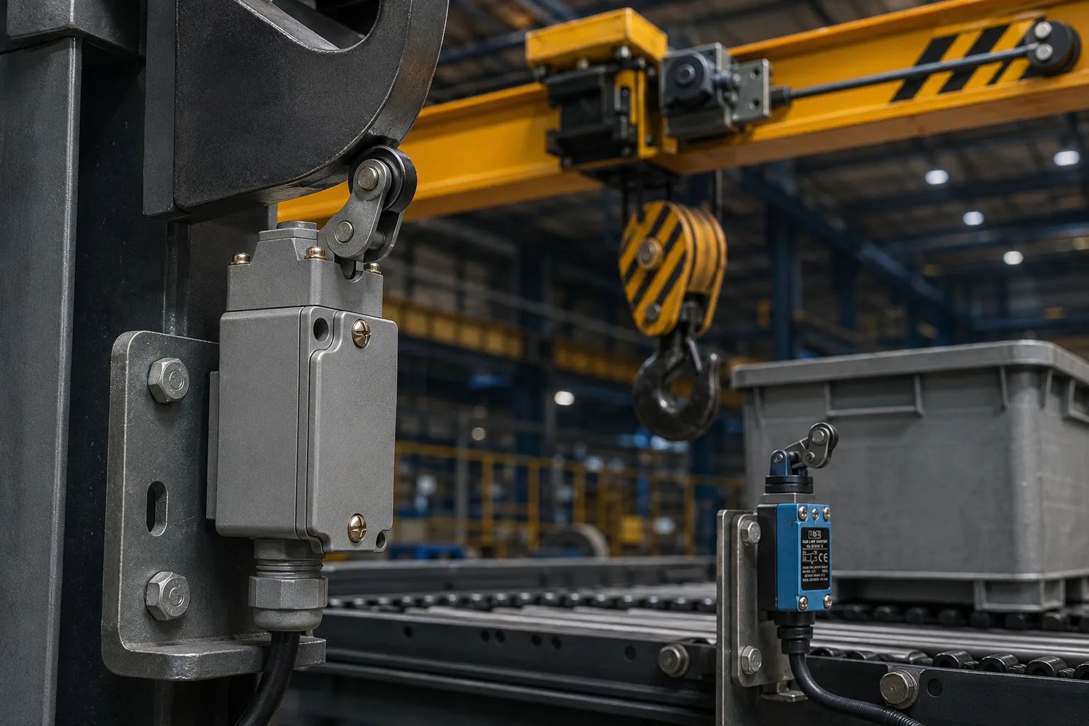
Limit switches used on cranes, conveyors and hoists must be selected around the actual motion, stopping point, environment and control logic. The right device should actuate reliably at the required position, provide the correct contact arrangement, tolerate mechanical shock and vibration, and remain accessible for inspection or replacement. A good starting point is the BCH Electric Limit Switches range, but the final choice should be made only after the machine duty and installation conditions are clearly defined.
Why limit-switch selection matters in material-handling systems
Cranes, conveyors and hoists depend on predictable movement. A bridge crane must stop before it reaches the end of travel. A hoist must not continue lifting after the hook block reaches its upper safe position. A conveyor may need to confirm that a guard, chute, diverter or transfer mechanism has reached a defined position before the next step begins. In each case, a limit switch turns mechanical movement into an electrical signal that the control circuit can use.
The device is small compared with the machine, but its effect is not. A poorly positioned actuator can be missed by the moving part. An unsuitable contact arrangement can reverse the intended logic. An enclosure that is not matched to dust, moisture or impact can fail early. These problems often appear as nuisance stoppages, over-travel, intermittent signals or repeated adjustment work during maintenance shutdowns.
For that reason, engineers should treat a limit switch as part of the complete sensing and control chain rather than as an isolated catalogue item. The switch, actuator, mounting bracket, wiring, contactor or relay logic, braking system and machine travel all have to work together.
What a limit switch does in a crane, conveyor or hoist
A limit switch changes the state of one or more electrical contacts when a moving machine part physically operates its actuator. The resulting signal can stop motion, permit the next sequence, trigger an alarm, reverse direction or confirm that a mechanism has reached a safe position. The exact function depends on the control circuit.
|
Application |
Typical detection point |
Typical control response |
|
Overhead or gantry crane |
Bridge or trolley approaching end of travel | Stop travel, reduce speed, or prevent further movement |
| Hoist | Hook block reaching upper or lower travel limit |
Interrupt lifting or lowering command |
|
Conveyor |
Belt misalignment arm, chute gate, diverter, guard or product position | Stop conveyor, signal PLC, or enable the next sequence |
| Transfer system | Carriage or shuttle reaching a defined station |
Confirm position and permit loading or unloading |
|
Material-handling machine |
Access door or guard position |
Prevent operation until the safe condition is confirmed |
For a broader view of how these devices fit into industrial automation, see What Are Limit Switches and How Do They Enhance Industrial Automation?.
Start with the machine movement, not the switch model
The most useful selection question is not “Which limit switch should we buy?” It is “What movement must be detected, at what point, and what must the control system do when detection occurs?” That sequence prevents the team from comparing models before the duty is understood.
- Define the moving part: bridge, trolley, hook block, gate, diverter, belt-tracking arm, carriage or guard.
- Define the required event: normal position confirmation, slow-down command, end-of-travel stop, emergency over-travel backup or interlock.
- Record the approach direction and speed of the moving part.
- Measure the available mechanical travel after the switch operates.
- Confirm whether the machine can coast after the control signal changes.
- Identify vibration, shock, dust, moisture, oil, temperature and washdown exposure.
- Confirm how maintenance personnel will reach, test and replace the switch.
Key selection factors for limit switches
1. Actuator type and direction of approach
The actuator is the part that the machine physically moves. Roller levers are often useful where a cam or moving member passes the switch. Plungers can suit direct, controlled contact. Rotary or lever arrangements may be appropriate when a wider operating angle is needed. The actuator must match the direction, speed and repeatability of the target movement. A switch that is electrically suitable can still fail in service if the actuator is struck from the wrong direction or forced beyond its intended travel.
2. Contact configuration
The circuit may require normally open, normally closed or changeover contacts. Normally closed logic is commonly preferred in functions where a broken wire should be detectable as a fault, but the control philosophy must be reviewed by the machine designer. For interlocking, position confirmation and redundant stopping functions, the number and arrangement of contacts can be as important as the enclosure or actuator.
3. Mechanical travel and over-travel
The target should operate the switch decisively but should not continue pushing it beyond the permissible travel. On cranes and hoists, machine momentum and brake response must be included in the calculation. The switch should be mounted early enough to allow the control and braking system to stop the movement before a physical end stop is reached.
4. Operating frequency and duty cycle
A switch used occasionally as a final travel limit faces a different duty from one used repeatedly for every conveyor cycle. High operating frequency affects mechanical wear, contact life and maintenance intervals. The expected cycles per hour and annual operating cycles should be documented before product selection.
5. Environmental protection
Material-handling areas can expose switches to dust, moisture, oil, metal particles, outdoor weather and mechanical impact. The enclosure, cable entry and sealing arrangement must match the site. Environmental protection should be checked from the product data and not assumed from appearance.
6. Mounting rigidity and repeatability
A flexible bracket, loose fastener or poorly aligned cam can create more trouble than the switch itself. The mounting arrangement should resist vibration and allow controlled adjustment. After commissioning, reference marks can help maintenance teams confirm whether the switch or target has shifted.
7. Electrical rating and control-circuit compatibility
The contact rating must suit the actual control load, including the characteristics of relay or contactor coils. Inductive loads can stress contacts differently from resistive test loads. The switch should be coordinated with the control voltage, protective device, wiring method and downstream logic.
When a limit switch controls or interlocks a motor circuit, the related BCH Electric contactor range may also be relevant to the overall design.
Application guide: cranes
Crane travel normally involves bridge movement, trolley movement and hoisting. Each axis can require normal operating limits and an additional final limit depending on the risk assessment and machine design. The control response may be a stop command, speed reduction, direction block or alarm. Limit switches should not be treated as a substitute for mechanical stops or other required protective measures.
|
Crane function |
What to verify |
Common mistake |
|
Bridge end travel |
Approach direction, stopping distance, bracket rigidity and access | Mounting the switch too close to the physical end stop |
|
Trolley travel |
Cam alignment, vibration and repeatability | Using a weak bracket that shifts during service |
| Hoist upper limit | Hook-block path, rope behavior and brake response |
Assuming the motor stops instantly after the signal |
|
Final over-travel limit |
Independent logic and physical separation from normal limit |
Using the same actuation point without reviewing redundancy |
For integrated motion-control solutions, review BCH Electric’s crane control panel category, including AC crane control panels and DC crane control panels.
Application guide: conveyors
Conveyor limit switches can confirm the position of chutes, gates, diverters, take-up mechanisms, guards and transfer devices. They may also be used with mechanical arms for belt misalignment detection. The application should be reviewed for product build-up, dust, vibration and accidental impact. The target must operate the actuator consistently without scraping, jamming or holding the switch under excessive force.
In sequence control, the switch signal should represent a real mechanical condition. For example, a gate-open signal should be generated only after the gate reaches the required position, not merely when the actuator begins moving. This distinction prevents the next step from starting too early.
Application guide: hoists
Hoist applications require careful attention to upper and lower travel, braking distance, rope stretch, block movement and load conditions. The upper travel limit is especially important because the moving hook block can approach fixed machinery. The switch and actuation mechanism should be inspected regularly for alignment and free movement.
A final limit should be treated as a protective backup rather than a routine stopping device unless the equipment design specifically states otherwise. Routine operation against a final limit increases wear and can hide problems in the normal control sequence.
Choosing the appropriate BCH Electric limit-switch family
The sitemap shows several BCH Electric product families that can support different machine duties. The correct family depends on the datasheet, actuator options, enclosure details, contact arrangement and site conditions.
General-purpose limit switches can be reviewed for standard industrial position-detection tasks where the mechanical and environmental duty fits the product specifications.
Heavy-duty NL Series limit switches are a logical page to evaluate for cranes, material handling and other demanding machine environments.
Precision limit switches may be relevant where compact, repeatable position detection is required and the application falls within the product limits.
Mini limit switches can be considered where installation space is restricted and the electrical and mechanical ratings remain suitable.
These internal links are intended to narrow the product path, not to replace engineering review. Product specifications and the machine risk assessment must remain the basis of selection.
Installation and commissioning checklist
- Confirm the switch part number, contact arrangement and actuator type against the approved drawing.
- Verify that the mounting surface and bracket are rigid and protected from unintended impact.
- Operate the machine slowly during initial alignment and observe the actuator movement.
- Check that the switch changes state before the machine reaches the unsafe travel limit.
- Measure actual stopping distance under realistic operating conditions where permitted by the commissioning plan.
- Verify control logic for normal operation, wire break, emergency stop and power restoration.
- Check cable gland, conductor termination, earthing and enclosure sealing.
- Confirm that the actuator returns freely after the target moves away.
- Record the final mounting position and test result for maintenance reference.
- Do not bypass the switch to complete production without an approved safety procedure.
Common mistakes that cause nuisance trips or early failure
- Selecting by current rating alone and ignoring mechanical duty.
- Allowing the moving target to strike the actuator at excessive speed.
- Mounting the switch where material build-up blocks the actuator.
- Using a flexible bracket that changes position under vibration.
- Ignoring machine coast and braking distance.
- Wiring the wrong contact and reversing the intended fail-safe logic.
- Choosing an enclosure without checking dust, water or oil exposure.
- Using the final over-travel switch as the normal stopping point.
- Leaving no safe access for inspection and replacement.
- Replacing a failed switch without investigating alignment or process causes.
The related BCH article on common industrial problems solved by limit switches can help maintenance teams connect symptoms with likely application issues.
Maintenance practices for reliable operation
Maintenance should focus on the complete actuation path. Inspect the switch body, mounting hardware, cable entry, actuator, target cam and surrounding structure. Look for looseness, corrosion, cracked components, bent levers, accumulated dust and changes in alignment. Functional testing should confirm both mechanical movement and electrical contact change.
The inspection frequency should reflect operating cycles, environmental severity and consequence of failure. A high-cycle conveyor in a dusty process may need more frequent checks than an infrequently used maintenance hoist. Repeated adjustment is a warning sign. It may indicate bracket movement, target wear, excessive vibration or an unsuitable actuator arrangement.
For additional selection criteria, refer to Top Features to Look for in Industrial Limit Switches and Best Limit Switches for Heavy-Duty Industrial Machines.
Frequently asked questions
Can one limit switch be used for both normal stopping and final over-travel protection?
It may be technically possible in some designs, but normal and final limits often serve different purposes. The machine designer should review the required independence, control logic and risk level. Do not assume that one device is sufficient without the approved design and risk assessment.
Which contact is better for a safety-related stop: NO or NC?
Normally closed circuits are often used because loss of continuity can be detected, but the correct architecture depends on the complete safety and control design. The contact configuration, monitoring method and applicable machine requirements should be decided by a qualified engineer.
Why does a crane continue moving after the limit switch operates?
The motor and mechanical system do not always stop instantly. Contactor release time, brake response, load, speed and machine inertia all contribute to stopping distance. The switch must operate early enough to account for this travel.
Can a limit switch directly switch a motor?
Limit switches are generally used in control circuits rather than to switch a motor power circuit directly. Check the product rating and use the required contactor, relay or control device for the motor duty.
How do I select between general-purpose and heavy-duty limit switches?
Compare mechanical strength, actuator options, enclosure protection, operating frequency, shock, vibration and environmental exposure. Then verify the exact BCH product datasheet for the intended application.
Where can I request BCH Electric product support?
After documenting the machine duty, actuator requirement, contact arrangement and environment, use the BCH Electric enquiry page to share the requirement with the relevant team.
Final recommendation
For cranes, conveyors and hoists, select limit switches by starting with movement and risk, then working through actuator type, contact configuration, stopping distance, environment, mounting and maintenance access. The product page should be the confirmation step, not the first step. A well-selected switch is one that operates consistently, gives the control system the right signal and can be inspected without creating new hazards.
Explore the complete BCH Electric Limit Switches range and the Detection & Sensing application page. For a project-specific discussion, submit the documented requirement through the BCH Electric enquiry form.
