
Quick answer
kVAR capacitors should be selected by checking the required reactive power correction, system voltage, duty type, harmonic level, step size, switching sequence, panel design and site conditions. The right capacitor is not chosen by kVAR value alone. It must match the electrical duty of the plant and the way the APFC panel will switch capacitor steps during actual load changes.
In industrial power factor correction, poor capacitor selection can lead to overheating, step hunting, nuisance trips, over-correction, reactor mismatch and shorter service life. Before comparing products, engineers should confirm the present power factor, target power factor, connected load pattern, harmonic content, voltage variation and available panel space.
What are kVAR capacitors?
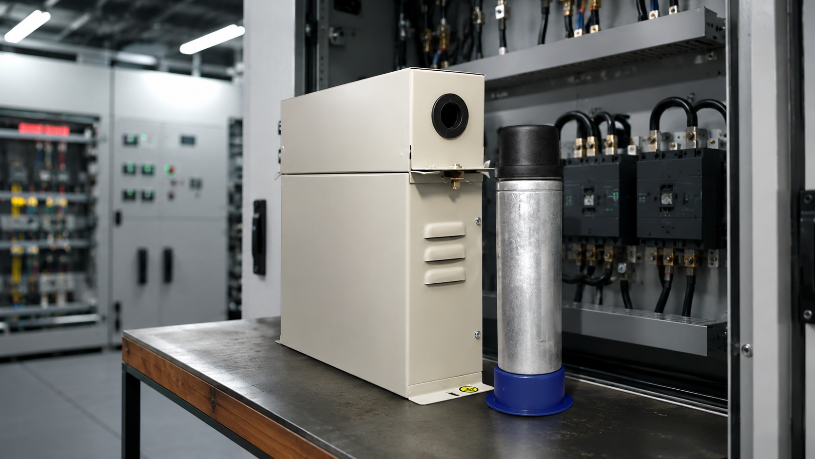
kVAR capacitors are low-voltage power capacitors used for power factor correction. They supply reactive power locally so that the electrical system draws less reactive power from the supply. This helps improve power factor, reduce unnecessary reactive current and support better use of electrical capacity.
In a plant, kVAR capacitors are usually used inside fixed capacitor banks or APFC panels. They may work with APFC relays, capacitor switching contactors, reactors, fuses, MCCBs, busbars, terminals and panel ventilation arrangements.
A capacitor may look like a single component, but its performance depends on the full system. Voltage, load pattern, switching frequency, harmonics, temperature and panel design all affect capacitor life.
Why does kVAR selection matter?
The kVAR value decides how much reactive power the capacitor can supply. If the value is too low, the system may not reach the target power factor. If the value is too high, the system may move toward over-correction, especially during low-load periods.
In APFC panels, the issue is not only total kVAR. Step size and switching sequence matter as well. A panel with poorly chosen steps may switch too often, fail to follow load changes or create large correction jumps. That can reduce performance and increase stress on capacitors and switching devices.
For teams starting with the basic concept, BCH’s article on kVAR capacitors for industrial power systems is a useful supporting read before moving into selection details.
Start with the existing and target power factor
The first step is to know the present power factor and the target power factor. Without this, capacitor sizing becomes guesswork.
Engineers should collect:
- Present power factor
- Target power factor
- Connected load in kW or kVA
- Load variation across shifts
- Peak and low-load conditions
- Billing or utility penalty requirements
- Existing capacitor bank details, if any
A plant that runs a steady load may need a different correction strategy from a plant where loads change frequently. Welding machines, compressors, motors, presses, HVAC systems and process equipment can all change the reactive power profile.
If the main question is how much correction is required, BCH’s guide on how to calculate required kVAR for power factor correction can support the calculation stage.
Match capacitor voltage with the actual system
Voltage rating is one of the most important checks in capacitor selection. The capacitor voltage should match the system and the expected operating condition, including voltage rise, detuning requirement and switching duty.
A capacitor selected too close to the nominal voltage may run hotter or fail earlier in a site with voltage fluctuation, harmonics or frequent switching. This is why the actual plant condition matters more than a generic catalogue match.
Before finalizing voltage duty, check:
- Nominal system voltage
- Maximum operating voltage
- Voltage variation
- Harmonic distortion
- Reactor use, if applicable
- Switching frequency
- Ambient temperature
- Panel ventilation condition
Capacitor duty should be reviewed with the complete APFC panel design, not separately from the site.
Check duty type and load pattern
A capacitor used in a steady load application does not face the same duty as a capacitor in a plant with frequent load changes. APFC panels switch capacitor steps in and out based on reactive power demand. Frequent switching increases electrical and thermal stress.
The duty becomes more demanding when:
- Load changes quickly
- Motors start and stop frequently
- Welding or nonlinear loads are present
- Capacitor steps switch often
- Ambient temperature is high
- Panel ventilation is weak
- Harmonics are present
- The plant operates for long hours
This is where the selection should move beyond a simple kVAR estimate. The capacitor must suit the way the plant actually operates.
Understand APFC panel step sizing
APFC panels use capacitor steps to match changing reactive power demand. Each step adds or removes a certain amount of kVAR. The APFC relay decides when to switch steps based on power factor, load current and system behavior.
Good step sizing helps the panel respond smoothly. Poor step sizing can cause step hunting, over-correction or slow correction.
For example, a plant with small, frequent load changes may need smaller step values for smoother correction. A plant with large block loads may need bigger steps, but the switching sequence must still avoid sudden correction jumps.
Before deciding APFC steps, check:
- Total required kVAR
- Minimum load condition
- Maximum load condition
- Load variation pattern
- Number of steps
- Smallest step size
- Switching sequence
- APFC relay capability
- Contactor and protection selection
- Harmonic and reactor requirement
BCH’s article on APFC panel step calculation is a natural next reference for readers who want to prevent under-correction and over-correction.
Why harmonic content changes capacitor selection
Harmonics can increase capacitor stress. In harmonic-rich systems, capacitors may draw higher currents, run hotter or interact with system impedance in a way that creates resonance risk.
This is common in plants with nonlinear loads such as drives, UPS systems, rectifiers, welding equipment, furnaces or electronic power converters. In such cases, engineers should not select capacitors without reviewing harmonic conditions.
Important checks include:
- Total harmonic distortion
- Dominant harmonic orders
- Type of nonlinear loads
- Reactor requirement
- Detuned capacitor bank requirement
- Capacitor current loading
- Panel heating
- Protection coordination
If harmonics are present, capacitor and reactor selection must be reviewed together. A capacitor that is acceptable in a clean system may not be suitable in a harmonic-rich plant.
Choose the right switching devices
Capacitor switching creates inrush current. Standard switching assumptions may not be enough for APFC duty. The switching device should be selected for capacitor switching behavior, not only by normal current.
In APFC panels, capacitor switching contactors are commonly used for switching capacitor steps. They help manage the stress that appears when capacitor banks are energized.
For related switching hardware, readers can review BCH’s capacitor switching contactor . For the wider APFC system, BCH’s APFC panel and APFC relay help connect capacitor selection with switching logic and automatic correction.
Check the panel environment
A capacitor selected correctly on paper can still fail early if the panel environment is poor. Heat is one of the biggest risks. Capacitors generate heat during operation, and APFC panels can become crowded with capacitors, contactors, reactors, busbars and wiring.
Review these site and panel conditions:
- Ambient temperature
- Panel ventilation
- Heat from reactors
- Space between capacitor units
- Cable routing
- Dust and contamination
- Moisture or condensation
- Service access
- Terminal tightness
- Earthing and protection
- Spare space for future steps
Panel design affects capacitor life. A good capacitor cannot perform reliably if it is installed in a hot, cramped or poorly ventilated cabinet.
kVAR capacitor selection checklist
| Checkpoint | What to verify | Why it matters |
|---|---|---|
| Present power factor | Existing PF under normal and peak load | Defines the correction requirement |
| Target power factor | Required PF after correction | Avoids under-correction or over-correction |
| Required kVAR | Calculated reactive power compensation | Sets the total capacitor bank size |
| Step size | Smallest and largest APFC steps | Controls how smoothly the panel responds |
| Voltage rating | System voltage and expected variation | Prevents capacitor overstress |
| Duty type | Switching frequency and operating hours | Affects heating and service life |
| Harmonics | THD and nonlinear load presence | Helps decide reactor or detuned design |
| Switching device | Capacitor switching contactor or suitable switching arrangement | Handles capacitor inrush current |
| APFC relay | Step logic and correction control | Prevents poor switching behavior |
| Panel condition | Ventilation, space and access | Reduces overheating and maintenance risk |
| Lifecycle support | Spares, service and documentation | Supports long-term uptime |
Common mistakes in kVAR capacitor selection
Many capacitor problems start before installation. The issue is usually an incomplete understanding of the load or panel duty.
Common mistakes include:
- Selecting only by kVAR value
- Ignoring voltage variation
- Ignoring harmonics
- Using poor step sizing
- Oversizing the capacitor bank
- Not checking low-load operation
- Ignoring reactor requirement
- Using unsuitable switching devices
- Installing capacitors in hot panels
- Leaving too little service space
- Not checking APFC relay settings
- Waiting for repeated trips before reviewing the selection
These mistakes can lead to overheating, step hunting, nuisance trips, capacitor bulging, fuse operation, poor power factor correction and avoidable downtime.
How kVAR capacitors fit into the APFC system
A kVAR capacitor is only one part of a power factor correction system. In an APFC panel, the capacitor works with the APFC relay, switching contactors, protection devices, reactors where required, busbars, wiring and ventilation.
The APFC relay measures the system condition and decides which capacitor steps to switch. The capacitor supplies reactive power. The switching contactor connects or disconnects the step. Protection devices handle fault conditions. The panel design supports safe installation and service.
For readers evaluating a complete system, BCH’s guide on building an APFC panel with BCH products can help connect the product pieces into a practical panel architecture.
What should engineers verify before final approval?
Before releasing a capacitor bank or APFC panel for procurement, engineers should verify the plant data and the panel design together.
Confirm:
- Present and target power factor
- Load profile across operating shifts
- Total required kVAR
- Step size and step sequence
- Voltage rating
- Harmonic content
- Reactor requirement
- Switching device selection
- APFC relay logic
- Panel ventilation
- Protection coordination
- Service access
- Spare availability
- Future expansion requirement
The draft source also recommends checking low-voltage panel assembly context and capacitor, relay, reactor and assembly data before publication or final selection.
If the plant condition is unclear, the load profile changes heavily, or harmonic content has not been checked, the project team can share site details through the BCH enquiry page or contact page.
Frequently asked questions
What are kVAR capacitors used for?
kVAR capacitors are used for power factor correction. They supply reactive power locally so the plant draws less reactive power from the supply, improving power factor and supporting better electrical capacity use.
How do I select the right kVAR capacitor?
Start with present power factor, target power factor, load kW, load pattern, voltage, harmonic content and APFC step requirement. Then check capacitor duty, switching sequence, panel environment and protection coordination.
Can kVAR capacitors be selected only by current rating?
No. Current rating alone is not enough. You also need to check voltage duty, required kVAR, harmonic content, APFC step size, switching frequency, panel temperature and site conditions.
Why is step size important in an APFC panel?
Step size controls how smoothly the APFC panel corrects power factor as load changes. Poor step sizing can cause over-correction, under-correction or frequent switching.
Why do capacitors overheat in APFC panels?
Capacitors may overheat because of harmonics, overvoltage, frequent switching, poor ventilation, high ambient temperature, reactor mismatch or overcrowded panel layout.
When are reactors needed with kVAR capacitors?
Reactors may be needed when harmonic content is present or when detuned capacitor bank design is required. The final decision should be based on harmonic study, plant load and system design.
What is the difference between fixed capacitors and APFC capacitors?
Fixed capacitors provide a constant amount of reactive power. APFC systems switch capacitor steps automatically according to changing load demand. APFC panels are more suitable where the load varies during operation.
Where should I go after calculating required kVAR?
After calculating required kVAR, review capacitor voltage duty, step size, harmonic conditions, APFC relay logic and panel design. Then compare the relevant BCH LT Power Capacitors and Power Factor Management products.
Final takeaway
kVAR capacitor selection should begin with the plant’s real power factor correction requirement, not the nearest catalogue value. The capacitor must match the voltage, load duty, harmonic condition, APFC step plan, switching device and panel environment.
A well-selected capacitor bank improves power factor correction and reduces avoidable service issues. A poorly selected one can create heating, nuisance trips, step hunting and premature failure. Start with clean plant data, confirm the harmonic and duty conditions, then choose the right BCH capacitor and APFC system components for the application.
