
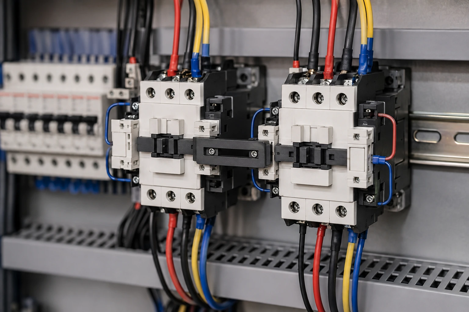
A reversing starter changes motor direction by changing the phase sequence, typically by swapping two phases between the forward and reverse power paths. That makes interlocking fundamental to the circuit: if both contactors close together, the switching arrangement can create a phase-to-phase short circuit.
Before designing the interlock, select the contactor for the real motor duty. Start with the BCH contactor product family and confirm the utilisation category, current, coil/control requirements and mechanical-interlock compatibility for the exact references being considered.
The Four Interlock Layers
| Layer | Function |
| NC auxiliary-contact interlock | Prevents the opposite coil circuit from energising while one contactor is active. |
| Mechanical interlock | Physically prevents both contactors from reaching the closed position together. |
| Control logic | Enforces the forward/reverse command sequence and any required delay. |
| Feedback monitoring | Confirms whether a contactor actually changed state and can detect abnormal behaviour. |
How a Forward-Reverse Contactor Circuit Works
The forward contactor applies the normal phase sequence to the motor. The reverse contactor is wired so that two phases are interchanged. Only one power path should be active at any time. The control circuit therefore has to prevent a reverse command from energising the reverse coil while the forward contactor remains closed, and vice versa.
This is more than a software-sequencing problem. Wiring errors, welded contacts, failed outputs or mechanical faults can defeat a command sequence, which is why conventional reversing starters commonly use both electrical and mechanical interlocking.
1. Electrical Interlocking With Normally Closed Auxiliary Contacts
Electrical interlocking is usually implemented by wiring a normally closed auxiliary contact from each contactor in series with the opposite coil circuit. When the forward contactor energises, its NC auxiliary contact opens the reverse-coil path. When the reverse contactor energises, its NC auxiliary contact opens the forward-coil path.
The important point is that the interlock depends on the actual contactor state, not only the requested command. Auxiliary-contact selection and wiring therefore need to match the contactor and control circuit being used.
2. Mechanical Interlocking Between the Contactors
A compatible mechanical interlock adds a physical barrier. If one contactor is mechanically closed, the interlock prevents the opposite contactor from closing at the same time. It provides a separate layer from the electrical control circuit.
Compatibility matters. Do not assume that two contactors with similar ratings can be mechanically interlocked together. Use the manufacturer’s approved accessory or combination for the exact product references.
3. PLC Logic Is Useful – but It Is Not the Only Barrier
A PLC can enforce command order, add a reversal delay, supervise permissives and generate diagnostics. Those functions are valuable, especially when the machine sequence is more complex than a simple push-button circuit.
However, the source guidance is explicit that software delay alone can be defeated by output faults, wiring errors or welded contacts. Where the risk assessment requires prevention of simultaneous closure, retain the appropriate hardwired and mechanical barriers rather than treating PLC logic as the sole interlock.
4. Add Feedback When the Application Needs State Verification
Feedback monitoring can tell the controller whether a contactor actually changed state. This becomes important when a machine must detect a contactor that failed to open or close rather than assuming the commanded state occurred.
Where the safety assessment requires it, use feedback devices and architectures appropriate to the required safety function. The source article specifically notes force-guided or safety-rated feedback where the risk assessment calls for it.
Reversal Delay and Plug Reversing
The motor may need time to slow before the opposite contactor is allowed to close. Reversing a rotating motor can produce a much more severe electrical and mechanical duty than ordinary starting. The correct delay depends on the machine, load inertia, torque requirement and selected control strategy.
Plug reversing at speed is a severe duty and can require AC-4 contactor selection. Check the applicable current, torque, machine stress and expected contact life rather than applying an AC-3 selection automatically.
For duty selection, use the BCH guide to AC-1, AC-3 and AC-4 contactor ratings together with the exact product catalogue data.
Select the Contactor From the Motor Duty, Not One Ampere Number
Record motor voltage, nameplate current, starting and reversing duty, starts or reversals per hour, acceleration time and load torque. These conditions determine whether the contactor is being asked to make, carry or interrupt current under a normal or severe switching duty.
The BCH contactor selection guide for industrial motor control provides a useful companion reference when selecting the forward and reverse contactors before the interlock hardware is finalised.
Check the Whole Starter Combination
The contactors do not protect the motor circuit by themselves. The starter combination also includes the overload function, short-circuit protective device, cable and motor. These elements must be reviewed together so normal starting and reversal can occur without unwanted operation while genuine faults are cleared within the intended limits.
For the relationship between the switching and protection functions, see How Motor Starters Work With Contactors and Overload Relays. For setting and coordination context, BCH also has a guide on MPCB trip settings and contactor coordination.
A Practical Design Workflow for Reversing Contactors
- Define the motor load, operating mode and required direction changes.
- Record supply voltage, frequency, phase arrangement and motor nameplate data.
- Determine the current and utilisation category for the actual forward/reverse duty.
- Select forward and reverse contactors whose published ranges cover the duty.
- Confirm compatible normally closed auxiliary contacts and the manufacturer-approved mechanical interlock.
- Define the control sequence, stop behaviour and any required reversal delay.
- Check overload placement, short-circuit protection and coordination for the complete starter.
- Add contactor-state feedback where the control or safety assessment requires it.
- Commission both the electrical and mechanical interlocks before enabling normal operation.
- Save the schematic, exact product references, interlock accessories, timing and test results in the panel record.
Worked Scenario: Conveyor That Reverses to Clear a Jam
Consider a conveyor that normally runs forward but must reverse briefly to clear a jam. The control system needs to prevent a reverse command from closing the reverse contactor until the forward contactor has opened and the required delay has elapsed.
The electrical interlock blocks the opposite coil while one contactor is energised. The mechanical interlock provides a separate physical prevention layer. PLC logic handles the sequence and delay, while feedback can verify that the forward contactor actually dropped out before the reverse command is accepted.
If the machine must reverse while the motor is still rotating, the designer also has to check whether the resulting duty moves the contactor selection into a more severe utilisation category. The right answer is based on the actual machine duty and manufacturer data, not simply the motor kW.
Commissioning Checks Before Energising the Machine
- Confirm the exact forward and reverse contactor references and mechanical-interlock accessory.
- With power isolated, prove the mechanical interlock prevents simultaneous closure.
- Check the NC auxiliary-contact wiring against the approved schematic.
- Confirm phase sequence and the intended motor direction for each contactor.
- Verify overload and short-circuit protective devices against the signed setting schedule.
- Test stop, restart and loss-of-control-power behaviour.
- Prove any reversal delay and feedback logic under controlled conditions.
- Record the final settings, timings and test results for maintenance.
Common Interlocking Failures and What They Reveal
If a reversing starter behaves unexpectedly, do not begin by changing delays or increasing protection settings. First identify the actual failed state: did a contactor remain mechanically closed, did an auxiliary contact fail to change state, did the PLC output remain active, or did a wiring change bypass the interlock?
A maintenance record should capture the contactor state, command state, feedback indication, trip device and event timing. That evidence is far more useful than a generic “starter fault” note and helps prevent the same undocumented modification from returning later.
What to Include in the Purchase Specification
Describe the motor and reversing duty before naming a preferred contactor. Ask the supplier to identify the exact forward/reverse references, utilisation category, operational voltage and current, coil/control voltage, auxiliary contacts, compatible mechanical-interlock accessory, terminal range and any tested coordination information relevant to the complete starter.
Use the current BCH product catalogues to verify the exact references and accessories. If the published data does not cover the intended reversing duty or combination, obtain application guidance rather than assuming equivalence.
FAQs: Reversing Contactor Interlocking
Is a mechanical interlock enough for a reversing starter?
For conventional reversing starters, the source guidance recommends both electrical and mechanical interlocking unless an approved design states otherwise. The two layers address different failure paths.
Can a PLC delay replace auxiliary-contact interlocking?
A PLC delay alone is not a complete substitute. Output faults, wiring errors or welded contacts can defeat a software-only sequence. Retain hardwired prevention appropriate to the risk.
Why is simultaneous forward and reverse contactor closure dangerous?
The reverse power path swaps two phases. If the forward and reverse contactors close together, the circuit can create a phase-to-phase short circuit.
Why might a reversing contactor need AC-4 selection?
Plug reversing at speed is a severe switching duty. The source guidance notes that this can require AC-4 selection, so the actual motor current, torque, machine stress and expected contact life must be checked.
Should the motor stop before the opposite contactor closes?
The motor may need time to slow before reversal. The required delay depends on the machine and duty; it should be defined from the application rather than copied from a generic timer setting.
What should be recorded for future maintenance?
Keep the control schematic, contactor references, auxiliary and mechanical-interlock details, reversal delay, feedback logic, protection settings and commissioning test results with the panel record.
