Quick answer
A DOL starter starts a motor by applying full line voltage directly to the motor terminals. When the start push button is pressed, the contactor coil is energized. The contactor closes its main contacts, the motor receives supply and starts running. An auxiliary contact keeps the coil energized after the start button is released. If the stop button is pressed or the overload relay trips, the coil circuit opens, the contactor drops out and the motor stops.
In a practical panel, the DOL starter is usually reviewed along with motor full-load current, coil voltage, overload relay range, short-circuit protection, enclosure type, number of starts per hour and site conditions.
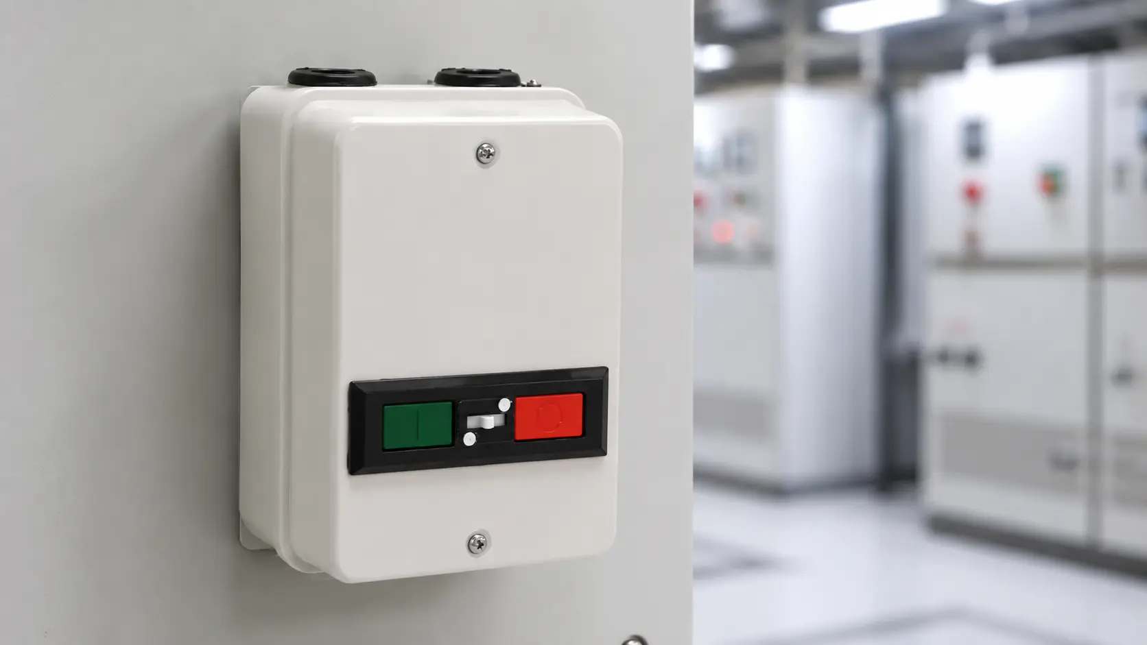
For product selection, BCH offers dedicated DOL starter options for motor-control applications. If the buyer is still comparing starter types, the broader motor starter category can help with the next level of selection.
What is a DOL starter?
A DOL starter is a motor starter that connects the motor directly across the supply line during starting. Because the motor receives full voltage immediately, the starting current is high compared with normal running current. That is why DOL starters are generally used where the motor, supply system and driven load can handle direct starting.
A basic DOL starter includes:
- A contactor for switching the motor supply
- An overload relay for motor overload protection
- Start and stop push buttons for control
- Auxiliary contact for holding the circuit
- Short-circuit protection through an MPCB, fuse or breaker as per panel design
- Enclosure, terminals and wiring accessories depending on the installation
The starter does not reduce starting current like a star-delta starter, soft starter or drive. Its job is to provide simple, direct motor starting with safe control and protection.
For a system-level explanation of how the surrounding devices work together, BCH’s guide on how motor starters work with contactors and overload relays is a useful supporting read.
Main parts in a DOL starter wiring diagram
A DOL starter wiring diagram normally has two sections: the power circuit and the control circuit.
Power circuit
The power circuit carries the motor current. It usually includes the incoming supply, short-circuit protection, contactor main contacts, overload relay and motor terminals.
The path is usually arranged like this:
Supply enters the starter panel. It passes through short-circuit protection such as an MPCB, fuse or breaker. From there, it goes through the contactor main contacts. The output then passes through the overload relay before reaching the motor terminals.
When the contactor closes, the motor receives full voltage. When the contactor opens, the motor is disconnected from the supply.
For related protection devices, readers can review BCH MPCB products, contactors and overload relays. These devices are often selected together because the starter must protect the motor as a complete system, not as isolated components.
Control circuit
The control circuit carries lower control current and decides when the contactor should energize or drop out.
A typical control circuit includes:
- Stop push button, normally closed
- Start push button, normally open
- Contactor coil
- Overload relay trip contact, normally closed
- Auxiliary contact for self-holding
- Control supply based on the selected coil voltage
When the start push button is pressed, current flows through the stop button, overload contact and start button to energize the contactor coil. Once the contactor closes, its auxiliary contact creates a parallel holding path around the start button. This keeps the coil energized even after the start button is released.
When the stop button is pressed, or when the overload relay trips, the control circuit opens. The contactor coil de-energizes, the main contacts open and the motor stops.
Sequence of operation in a DOL starter
A DOL starter works in a clear sequence. Understanding this sequence helps during wiring review, commissioning and troubleshooting.
-
Supply is available
The incoming supply is available at the starter input. The motor is still off because the contactor main contacts are open. The control circuit is ready, provided the stop button and overload relay trip contact are closed.
At this stage, the panel should be checked for correct supply voltage, proper earthing, correct control voltage and secure terminal connections.
-
Start button is pressed
When the operator presses the start button, the control circuit becomes complete. Current reaches the contactor coil.
The coil creates a magnetic field and pulls the contactor mechanism in. This closes the main power contacts.
-
Motor receives full line voltage
Once the contactor main contacts close, the motor is connected directly to the supply. The motor draws high starting current for a short time and accelerates toward rated speed.
The starting current must be acceptable for the motor, cable, protection device and supply system. This is one reason DOL starters are not suitable for every motor or every site condition.
-
Holding contact keeps the motor running
After the start button is released, the auxiliary contact keeps the contactor coil energized. This is called the holding circuit or seal-in circuit.
Without this auxiliary contact, the motor would run only while the start button is physically pressed.
-
Motor runs under normal load
During normal running, the overload relay monitors current. If the motor current stays within the set range, the starter continues to run.
The overload relay setting should be based on the motor full-load current shown on the nameplate and the applicable design practice. BCH’s article on overload relay setting for industrial motors can help readers understand the basics before final verification.
-
Stop button or overload trip opens the circuit
When the stop button is pressed, the control circuit opens and the contactor coil loses supply. The main contacts open and the motor stops.
If the motor draws excess current for too long, the overload relay trips. This also opens the coil circuit and stops the motor. The cause should be checked before resetting the starter.
Where DOL starters are commonly used
DOL starters are commonly used for motors where direct starting is acceptable and the starting current does not create a problem for the supply or driven equipment.
Typical applications include:
- Pumps
- Fans and blowers
- Compressors
- Conveyors
- Small and medium industrial machinery
- Agricultural motor applications
- General motor-control panels
For pump applications, the starter selection should also consider starting frequency, dry-run risk, voltage fluctuation, site environment and maintenance access. BCH’s article on single-phase DOL starter for water pumps is useful for pump-focused requirements. The pump controller category may also be relevant when the requirement is more pump-centric than general machinery-centric.
When a DOL starter may not be the right choice
A DOL starter is simple and dependable when used correctly, but it is not suitable for every motor.
It may not be the best choice when:
- The motor rating is too high for direct starting on the available supply
- The driven load cannot handle sudden starting torque
- The site has frequent starts and stops
- The supply system is weak or sensitive to voltage dips
- The application needs controlled acceleration or deceleration
- The motor needs advanced protection or monitoring
In such cases, the buyer may need to compare DOL starters with other starter types. BCH’s guide on choosing the right motor starter for different motor ratings can help readers move from general understanding to product selection.
How to select a DOL starter
A DOL starter should not be selected only by a current rating printed in a catalogue. The rating matters, but the application decides whether the selection will work reliably.
Check these points before finalizing the starter.
Motor rating and full-load current
Start with the motor nameplate. Note the HP or kW rating, voltage, phase, frequency and full-load current. The overload relay range should suit the motor full-load current.
Supply and control voltage
Confirm the supply voltage and the control voltage. The contactor coil voltage must match the control circuit. A wrong coil voltage can cause failure, chatter or non-operation.
Starting frequency
Check how often the motor starts in one hour. Frequent starting creates heat and mechanical stress. This affects starter selection, contactor life and overload behavior.
Load type
A pump, compressor, conveyor and fan do not behave the same way during starting. The driven load affects starting current duration, acceleration time and mechanical stress.
Short-circuit protection
The starter should be coordinated with the correct short-circuit protection. Depending on the design, this may involve an MPCB, fuse or breaker.
Overload relay setting
The overload relay should be set according to the motor full-load current and verified as per the applicable design requirement. A wrong setting can cause nuisance tripping or fail to protect the motor.
Enclosure and site conditions
Dust, moisture, heat, vibration, panel space and cable routing can all affect the final selection. A starter that works in a clean indoor panel may not be suitable for a pump house, dusty plant area or high-temperature installation.
Product variants to review
Different installations may need different DOL starter variants. Buyers can review BCH options such as Auto Start DOL Starter, Industrial DOL, and Mini Manual DOL Starter depending on the application, control requirement and panel arrangement.
Common mistakes in DOL starter selection
Many DOL starter problems are not caused by the starter itself. They usually come from incomplete selection, poor wiring, wrong settings or weak commissioning checks.
Common mistakes include:
- Choosing the starter only by motor HP
- Ignoring motor full-load current
- Selecting the wrong contactor coil voltage
- Setting the overload relay too high or too low
- Ignoring starting frequency
- Using weak or loose control wiring
- Ignoring phase loss or voltage imbalance
- Not checking panel ventilation and ambient temperature
- Treating pump applications like general machinery applications
- Replacing parts before checking the root cause of repeated trips
If a starter is already installed and the site is facing nuisance tripping, contactor chatter, overheating or reset issues, BCH’s guide on troubleshooting common DOL starter issues can support the maintenance journey.
Practical field checklist before final selection
Before approving a DOL starter, collect these details:
- Motor HP or kW
- Motor full-load current
- Supply voltage and phase
- Control voltage
- Application type
- Load behavior during starting
- Number of starts per hour
- Pump-specific conditions, if applicable
- Ambient temperature
- Panel space and enclosure requirement
- Cable size and routing
- Protection device requirement
- Overload relay range
- Maintenance access
- Any history of nuisance trips or motor failure
This information makes the product conversation more useful and reduces the risk of selecting a starter that looks correct on paper but fails in daily use.
Frequently asked questions
What is a DOL starter used for?
A DOL starter is used to start and stop an induction motor by connecting it directly to the supply. It is commonly used for pumps, fans, compressors, conveyors and machinery where direct starting is acceptable.
How does a DOL starter work?
When the start button is pressed, the contactor coil energizes and closes the main contacts. The motor receives full supply voltage and starts. An auxiliary contact keeps the coil energized. When the stop button is pressed or the overload relay trips, the coil circuit opens and the motor stops.
What are the main parts of a DOL starter?
The main parts are the contactor, overload relay, start push button, stop push button, auxiliary contact, short-circuit protection and enclosure. The exact arrangement depends on the panel design and application.
Can a DOL starter be selected only by motor HP?
No. Motor HP or kW is only the starting point. The final selection should also check full-load current, supply voltage, control voltage, overload relay range, starting frequency, site conditions and protection coordination.
Why does a DOL starter trip repeatedly?
Repeated tripping can happen because of overload, wrong overload setting, phase loss, voltage imbalance, mechanical load problems, loose wiring, high ambient temperature or a starter selected below the actual duty requirement.
Is a DOL starter suitable for pumps?
Yes, DOL starters are commonly used for pump applications when the motor and supply can handle direct starting. Pump-specific conditions such as dry-run risk, voltage fluctuation, frequent starts and site environment should be reviewed before selection.
When should I contact BCH for support?
Contact BCH when the motor duty is unclear, the site has frequent starting, pump-specific conditions, high ambient temperature, tight panel space, voltage fluctuation or repeated nuisance trips. Share the motor rating, full-load current, supply voltage, control voltage, application and site conditions through the BCH enquiry page or contact page.
Final takeaway
A DOL starter is simple only when the application is simple. For a reliable installation, the wiring diagram, control sequence, contactor, overload relay, short-circuit protection and motor duty must be reviewed together.
Start with the motor nameplate and site condition. Then confirm the control voltage, overload range, protection device, number of starts per hour and enclosure requirement. After that, compare the right BCH DOL starter option for the actual installation instead of choosing only by motor rating.
