
Quick answer
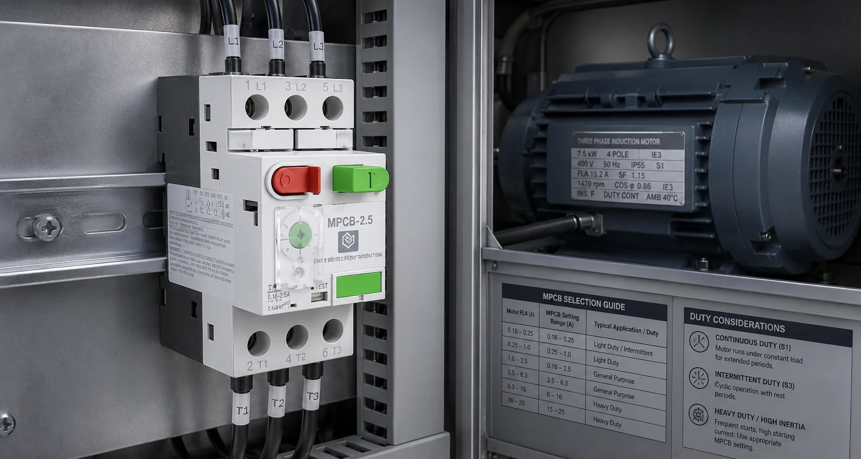
Select an MPCB whose adjustable thermal range includes the motor nameplate current. Then confirm that the device can tolerate the motor’s starting current, safely handle the prospective short-circuit level, and coordinate with the selected contactor and upstream protection. Motor kilowatts or horsepower can help create an initial shortlist, but they should not replace the actual motor current, starting method, duty cycle and installation data.
The correct MPCB is therefore not simply the smallest or largest range that contains the motor current. It is the device whose thermal setting, magnetic response, breaking capacity, accessories and tested coordination suit the complete motor feeder.
What an MPCB does in a motor feeder
A motor protection circuit breaker combines adjustable overload protection, short-circuit protection and manual switching in one compact device. It is designed around motor behaviour, including the need to carry legitimate starting current without unnecessary tripping.
An MPCB does not perform every control function in a starter. Where the motor must start and stop remotely, operate automatically or switch frequently, the feeder normally also requires a compatible contactor. For a wider explanation of the complete arrangement, read how motor starters work with contactors and overload relays.
For a side-by-side explanation of how each device protects a motor circuit, read MPCB vs MCB vs Overload Relay for Motor Protection.
Inputs required before MPCB selection
|
Input |
What to record |
Why it matters |
|
Motor current and voltage |
Nameplate current at the intended voltage and connection |
Defines the required adjustable thermal range |
|
Starting method |
Direct-on-line, star-delta, soft starter, VFD or another method | Changes the starting current and acceleration pattern |
|
Acceleration time |
Time taken to reach normal operating speed |
A long start can cause thermal or magnetic operation |
|
Duty and starts per hour |
Continuous, intermittent, reversing, inching or frequent-start duty |
Repeated starts can create heating that one-start calculations miss |
|
Prospective fault current |
Calculated fault current at the panel or feeder point |
Must remain within the applicable breaking and coordination ratings |
|
Contactor reference |
Exact product, utilization category and coil voltage |
Required for tested coordination and switching duty |
|
Ambient conditions |
Panel temperature, ventilation, altitude, dust and moisture |
May affect thermal performance, reliability and derating |
|
Cable data |
Length, size, conductor material and installation method |
Affects voltage drop, fault current and conductor protection |
Step 1: Start with motor nameplate current
The motor nameplate current at the actual supply voltage and connection is the most useful starting value. Avoid selecting the MPCB from motor kilowatts alone because motors with the same output can have different efficiencies, power factors, service factors and current values.
Shortlist an MPCB range that contains the nameplate current. The required setting should fall within a clear and usable part of the adjustment scale. Do not automatically select the widest range merely because it includes the motor current; a poorly matched range can make commissioning and later verification less clear.
Set the thermal adjustment according to the motor data, application conditions and the manufacturer’s instructions. Raising the setting only to suppress repeated trips can leave the motor under-protected.
Step 2: Check starting current and acceleration time
A motor can draw several times its running current while starting. The MPCB must distinguish this legitimate temporary current from a genuine short circuit or stalled condition. This is why the time-current characteristic and magnetic response matter as much as the adjustable overload range.
Direct-on-line starting may create a high inrush for a relatively short period. A high-inertia fan, loaded conveyor or pump starting after a long shutdown may accelerate more slowly. Star-delta, soft-starter and VFD applications produce different current patterns. The selected protection must be checked against the actual starting method rather than a generic assumption.
When the acceleration time is too long, the right answer may not be a higher MPCB setting. The installation may need a different starting method, mechanical correction, supply improvement or a review of the driven load.
Step 3: Include motor duty and starts per hour
Two motors with the same nameplate current can require different protection decisions if their operating duties are different. A continuously running pump, a reversing machine and a conveyor that starts repeatedly during each shift do not produce the same thermal pattern.
Record starts per hour, average run time, reversing or jogging requirements and the consequence of a trip. Frequent starts can increase motor, contactor and protective-device heating even when each individual start appears acceptable.
The switching device must also suit the load duty. Use the BCH contactor selection guide for industrial motor control when checking utilization category and operational duty.
Step 4: Verify prospective short-circuit current
The available fault current at the installation point must not exceed the applicable short-circuit rating of the selected device or the declared rating of the coordinated combination. This value depends on the transformer, upstream network, cable impedance and panel location.
Do not confuse the adjustable motor-current range with short-circuit breaking capacity. They describe different functions. The overload setting protects the motor against sustained overcurrent, while the breaking and coordination data address fault-energy interruption.
Long feeder cables can reduce the fault current seen at the motor end while also increasing voltage drop during starting. Both effects should be included in the design review.
Step 5: Check coordination with the contactor
An MPCB and contactor should be treated as a tested combination, not as two devices chosen independently by matching ampere labels. Coordination data confirms how the devices behave together during a short circuit and whether the starter can be returned to service after the fault is cleared.
Use the exact MPCB and contactor references shown in the manufacturer’s tables. A substitute contactor with the same nominal current may have different withstand, utilization-category or short-circuit performance.
Step 6: Review ambient and enclosure conditions
Thermal protection is affected by the environment around the device. High panel temperature, restricted ventilation, closely packed heat-producing components, altitude and dust can reduce operating margins or require derating.
The enclosure layout should provide the clearances and ventilation stated for the selected products. Cable entry, terminal access and the position of adjacent contactors or power devices should be reviewed before the bill of material is frozen.
Worked MPCB selection example
Assume a motor nameplate shows 14.2 A at the intended supply voltage. The first step is to shortlist an MPCB range that includes 14.2 A and allows the required setting to be applied clearly.
Next, check the motor starting method and acceleration time against the MPCB characteristic. If the motor is a high-inertia fan or a heavily loaded pump, a long start may create a trip even though the running current fits the selected range.
Then calculate the prospective fault current at the panel and confirm that it is within the relevant rating. Finally, verify documented coordination for the exact MPCB-contactor combination.
This example demonstrates the workflow only. Cable size, voltage drop, ambient temperature, service factor, starting frequency and enclosure conditions still require project-specific review.
A practical MPCB selection workflow
- Define the driven load, operating mode and required continuity of service.
- Record supply voltage, frequency, phase arrangement and earthing system.
- Read the motor nameplate current at the intended voltage and connection.
- Record starting method, acceleration time, starts per hour and load behaviour.
- Calculate prospective fault current and check cable withstand.
- Shortlist MPCBs whose adjustable ranges include the motor current.
- Compare starting current and duration with the published trip characteristic.
- Verify contactor compatibility and tested coordination.
- Review enclosure temperature, ventilation, terminals and accessibility.
- Document the selected reference, final setting, test method and approval.
Common MPCB selection errors
- Selecting only from motor kilowatts and ignoring the actual nameplate current.
- Choosing the highest adjustable range that happens to include the motor current.
- Treating the overload setting as the short-circuit breaking rating.
- Ignoring starting current, acceleration time or repeated-start duty.
- Assuming every contactor with the same current rating is coordinated.
- Forgetting cable voltage drop and fault-current effects on long feeders.
- Increasing the setting after nuisance trips without investigating the cause.
- Substituting a device without checking current manufacturer data.
Installation and commissioning checks
Correct selection can still fail in service if installation quality is poor. Check conductor size, strip length, lug or ferrule, tightening torque and terminal capacity. Maintain the product clearances and prevent neighbouring components from creating unrealistic heat around the MPCB.
Before energisation, verify the exact device references, pole arrangement, accessories, protective-earth continuity and control logic against the approved drawing. Confirm that the adjustable setting matches the signed schedule.
During commissioning, measure starting and steady-state current under representative load. Record individual phase values where imbalance matters. Testing should be carried out by competent personnel using suitable instruments and protective equipment.
What repeated tripping may indicate
Repeated trips should be investigated, not bypassed. An immediate trip may indicate a short circuit, locked rotor, severe inrush or an unsuitable magnetic response. A trip after several minutes may point to overload, extended acceleration, phase imbalance, high ambient temperature or a resistive connection.
Record the trip timing, process condition, motor current, panel temperature and indication before resetting. Change one verified factor at a time instead of increasing the setting and losing the evidence.
Where a separate overload relay is part of the starter, the BCH overload relay reset and troubleshooting guide provides a useful diagnostic sequence.
How to write the purchase specification
A clear specification should describe the motor application before naming a product. State the motor voltage, current, duty, starting method, environment, expected fault current and required switching arrangement.
Rated operational voltage and frequency
Adjustable motor-current range
Applicable short-circuit or breaking rating
Magnetic trip behaviour
Number of poles
Compatible contactor and coordination type
Required auxiliary or trip accessories
Terminal range and enclosure conditions
Catalogue, trip-curve and commissioning documentation
Use the BCH download centre for current literature. For an application-specific recommendation, submit the motor, feeder and fault-level data through the BCH enquiry page.
Frequently asked questions
Should an MPCB be set above the motor full-load current?
The setting should follow the motor nameplate, application conditions and manufacturer instructions. Increasing it simply to stop trips can leave the motor under-protected.
Can I select an MPCB only from motor kW?
No. Motor kW can support an initial estimate, but the actual nameplate current, voltage, connection and duty are more reliable selection inputs.
Does cable length affect MPCB selection?
Yes. Cable impedance affects starting voltage drop and the fault current available at the motor end.
Why is contactor coordination important?
It confirms how the MPCB and contactor behave together during a fault. Similar current labels do not prove that two references are a tested combination.
Can an MPCB be used without a contactor?
Yes, where local manual switching is sufficient. Remote, automatic or frequent switching usually requires a suitable contactor.
Final takeaway
Select an MPCB from the motor nameplate current, but approve it only after checking starting behaviour, duty, fault level, cable conditions, ambient temperature and coordination with the contactor. This system-based method produces a selection that can be commissioned, reviewed and maintained with confidence.
Before finalising the feeder schedule, compare the exact products in the BCH MPCB range and confirm the supporting data in the motor control product catalogue.
